Moses Ludel
-
Posts
4,447 -
Joined
-
Last visited
Content Type
Profiles
Forums
Blogs
Store
Articles
Gallery
Everything posted by Moses Ludel
-
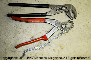
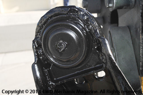
 When you work with brake, fuel and vacuum steel lines and fittings, you need the right wrenches! The quickest way to round the corners on tight or frozen flare nuts is with an open ended wrench. The recommended tool for flare nuts is, not surprisingly, a "flare nut wrench". Even with a flare nut wrench, there are times when frozen brake line nuts or old fuel line flare nuts will simply not want to come loose. The hex corners begin to round, the sign of real trouble ahead! I have high quality Bonney flares wrenches, a backup set of Craftsman flare nut wrenches and several chain wrenches—including a small, Wheeler Manufacturing chain wrench from the 1960s. That Wheeler chain wrench has saved my hide more than once, and it is probably my most versatile tubing work tool: Click to enlarge photos...Forum members can view all photos...If you're visiting, consider joining the forums—it's free! In a pinch, if the chain links are short enough, you can grip a softening flare nut. A chain wrench can also grip the base of a collapsed oil or fuel filter! My small chain wrench will grip a rusted brake flare nut securely, and that's small. It will also grip a collapsed oil filter canister near its solid base. There is also this Vise Grips model: http://www.amazon.com/s/ref=nb_sb_noss?url=search-alias%3Delectronics&field-keywords=Vise+Grips+chain+wrench. It's useful and contemporary, although its chain link size will only drop to 5/8" diameter—okay for hardware but not good enough for smaller brake tubing nuts and most fuel fittings. The side benefit of the Wheeler chain wrench is that when used properly, it does not leave a mark on the steel fitting nut! I've used these wrenches on high-end restoration work where the OEM hardware must appear original. You simply cannot achieve this with higher torque settings and a flare nut wrench. Even the most expensive flare nut wrenches will, by design, spread under load. A tip and caution: Wrap the hardware with a layer of shop towel before gripping with the chain wrench. This will help protect the surface (although it will shred the towel!). Modern chain link wrenches with a toothed, flat leverage point are very rough on hardware and will leave marks if not used with extreme caution...See my Wheeler Manufacturing wrench's design (above), much easier on corners and flats of the nuts and other hardware! So the next time you're at a garage sale, estate auction or used tool source, keep your eye open for a Wheeler Manufacturing chain wrench and other specialty tools "from the day". They truly do not make smaller chain wrenches like they used to... Trust this helps your tubing flare nut and stuck oil filter situations! Moses


-
EFI Fuel Filter Upgrade And Other Fixes
Moses Ludel replied to RareCJ8's topic in 1972-86 AMC/Jeep® CJ and Jeepster Models
This sounds really slick. For reference, the RPM 350 rates 300 GPH flow at a 4-micron filtration level. This is great for fine filtration plus adequate fuel flow. Again, Mark's injectors require 24 lb/hr X 6 cylinders = 144 lb/hr. Gasoline weights approximately 6.2 lb. per U.S. gallon, so flow demand for the stroker six at maximum injector flow (something like wide open throttle under severe load and then some!) would be 23.22 gallons per hour. That said, this filtration should handle a dozen 4.6L stroker sixes with these 302 Ford V-8 injectors! And with 4-micron filtering...This is really tight filtration, designed for high performance and racing fuel supply systems: The RPM 350 is rated 260 PSI maximum pressure!!! Did FST indicate filter lifespan with typical pump gas and a clean, capped system? How do you know when to change a filter—pressure drop? Is there a bypass function in the event of clogging or is this 100% flow through the filter at all times? I would think 100% flow through the filter, as you don’t want injectors exposed to unfiltered fuel at any time. Am I right? There should be plenty of filter media (surface area) in these filter canisters for reasonable filter life. OEM filters, from everything we’ve researched, must be 10 micron at best. FST's RPM 350 is much finer yet flows plenty of fuel! If you keep your tank clean and capped (it’s sealed, too), the filters should last. The mounting bracket and ports provided are for racing applications. FST is known in off-road racing circles and the high performance/racing industry. For the pre-filter, I would go back to the CARQUEST filter catalog and check out the threaded filters for the G.M. TBI applications. As you share, the pick-up side of the system does not require high pressure rating, and the G.M. common TBI systems operate at 9-14 PSI regulated pressure. These filters have threads (common fuel pipe type) at each end of the filter, and even if you need adapter fittings, you would still have quick removal/replacement capability. This filter should have more than enough flow, target a 350 or 454 V-8 engine application. The takeaway for all of us is that you should keep the fuel system as clean as possible at all times. Capped systems with EVAP should have all of the EVAP hoses and the canister in top condition. Keep dirt, trail dust and Nevada alkali powder out of that pristine new Aero tank, Mark... Buy yourself a set of quality flare nut wrenches, maybe two of each for the common sizes. I recommend carrying a small plumber's chain wrench, too! I've had a small Wheeler Manufacturing chain wrench, gifted to me in 1970 by a plumbing supply sales rep when I worked as a light- and medium-duty truck fleet mechanic. This tool has performed wonders for forty years, on everything from vintage British motorcycle chrome fork head plugs (high torque, hex headed and irreplaceable!) and stuck spin-on oil filters with collapsed canisters, to frozen brake tubing flare nuts! Here's a link to photos of the tool and my flare nut wrenches at the "The Right Tools and Equipment" forums: http://www.4wdmechanix.com/forums/index.php/topic/81-chain-wrenches-and-flare-nut-wrenches-for-tubing-nuts/ There is also this Vise Grips model: http://www.amazon.com/s/ref=nb_sb_noss?url=search-alias%3Delectronics&field-keywords=Vise+Grips+chain+wrench. In a pinch, if the chain links are short enough, you can grip a softening flare nut. A chain wrench can even grip near the base of a collapsed oil or fuel filter! My small Wheeler chain wrench will grip a rusted brake flare nut securely, and that's small. The same tool will also grip a collapsed oil filter canister near its base. The Vise Grips tool will only drop to 5/8" diameter, too big for most brake—or even fuel—tube fittings. Moses -
EFI Fuel Filter Upgrade And Other Fixes
Moses Ludel replied to RareCJ8's topic in 1972-86 AMC/Jeep® CJ and Jeepster Models
This all sounds good, Mark...I'm assuming you've been running 5/16" to this point, not 3/8"? Also, for clarification, when you hook up the auxiliary pump and have it set to run as a backup, you mention an extra pickup in the tank. That second pickup drops to near the floor of the tank and is also protected by a sock filter, right? So, the only distinction when you switch over is that the external Mopar EFI conversion kit pump is pulling from outside the tank—like with the EFI conversion kit method. With the switchover, you're still using the PCM signal to activate the external fuel pump, right? I'm very impressed that you're taking the fuel system to this level, as fuel supply is critical on an off-pavement, destination 4x4. Your photos will be helpful and valued when you get to that stage! Moses -
Mopar EFI Conversion Fuel Pump Troubles
Moses Ludel replied to RareCJ8's topic in 1972-86 AMC/Jeep® CJ and Jeepster Models
Mark, I looked at the product, drilled down, there’s no mention of pressure rating. If this will handle 80 PSI or more pressure without restricting flow, it could work. (Your EFI fuel regulator setting is well below this figure.) I would think 100 micron filtration could be okay as a pre-filter (before the pump) with a pickup sock and return flow to the tank. The idea is to prevent clogged injectors, and 100 micron is marginal. The filter is serviceable, a plus for your kind of use. With ready access and ease of service, you’d be a happy camper on that note. K&N has a series of high performance stainless fuel filters like the one you sought out. In the K&N lineup, ratings range from 25-100 micron—100 micron for gasoline is not that exciting, and this would be used in an engine where flow rate (GPM or GPH) is crucial. Here are K&N's offerings: http://www.knfilters.com/news/news.aspx?id=3366 Make sure of the pressure and flow rating (without significant pressure drop across the filter). 100 micron, by itself, would only protect injectors to a minimal degree. The range from 25-100 micron filtration is about flow rate and maintaining pressure in the system. OEM filters are much finer filtration than 100 micron. Your volume and flow must meet a 4.6L-5.0L engine's injector flow needs (24 lb/hr @ 39 PSI) after the filter. To know your maximum (ever) fuel demand, start with the premise that each injector can flow 24 pounds of fuel per hour. You have six injectors, so multiply 6 x 24 = 144 pounds per hour maximum flow. If gasoline weighs 6.2 pounds per U.S. gallon, you divide 144 by 6.2 = 23.22 approximate gallons of fuel flow per hour! So, you could get by with a filter capable of, say, 25 gallons per hour flow for maximum demand. If the filter manufacturer provides a GPM rating, simply multiply the GPM figure times 60 to determine GPH. If your fuel supply pressure were much above the 302 V-8 injector's 39 PSI pressure rating, you would need to add fuel demand accordingly. Something to put into perspective: What is the maximum rate of fuel you have ever burned with a Jeep inline six under load? Can you imagine burning fuel at the rate of 25 gallons per hour, even under hardcore 'wheeling conditions or trailering? Flow rate reflects maximum fuel demand regardless of the time interval. It could be just an instant, like wide open throttle acceleration in a passing situation under load. Fuel flow rate and pressure must be on tap every millisecond of the hour! Your 4.6L engine with the 252 camshaft and reasonable rpm ceiling could tolerate a 10-25 micron filter as long as the manufacturers' flow and pressure ratings are adequate...If absolute cleanliness at the injectors is the point, go with 10-25 micron on the post-pump side—with enough flow capacity and high enough PSI rating to handle your pump's pressure and fuel injector flow rating and demand. Note: Since your two-rail pump/supply pressure is regulated, with excess fuel returned to the tank, the actual line pressure is only equal to the rail regulator's PSI setting as read at the Schrader port. Here is a high performance website that recommends 90-micron as a "pre-filter" only—plus a 10-micron post filter. You must have adequate flow in any case. This outfit also offers a very nice dual pump/backup system (somewhat pricey by the time you factor filters into the package), which I discussed earlier. Scroll to the bottom at the website page for filter information: http://www.flyefii.com/add_components/additional_comp.htm#Filter Trust this is helpful, Mark... Moses -
Hi, Ty...For those unfamiliar with the Sonnax upgrades for RWD Chrysler transmission on Jeep and Dodge Ram trucks, see my article: http://www.4wdmechanix.com/Survival-Upgrades-for-Jeep-and-Dodge-Ram-Automatic-Transmissions.html. I'm very pleased with the Sonnax upgrades for our Ram 3500 48RE transmission, which include the manual valve, line pressure valve, the detent ball/sleeve and a piston upgrade—each without removal of the transmission or a major teardown...If you want your RE or RH transmission to survive, read the article at the "Automatic Transmission Workshop"! Your A-518 automatic is the first 727 Torqueflite-derived RWD Chrysler platform. Chrysler introduced the A-518 in 1988 and used it through 1996 on some applications. (42RE and 46RE were essentially the replacements for the A-518 in trucks.) The A-518 has many similarities in design and parts layout to both the A-727 Torqueflite 3-speed and the later RE 4-speed overdrive transmissions. Jeep 30RH and 32RH transmissions are also similar, but like the lighter A-500, their platform is the Chrysler 904/999 three-speed. The A-518 and later RE transmissions have the 4th gear overdrive built into the transmission unit and cases, and control for overdrive is solenoid based. As for stamina, the A-518 four-speed overdrive became a muscle car retrofit when built to performance standards. This replaces an A727 three-speed, modifying driveline length and the rear motor mount to fit. JVX Racing specializes in this conversion and makes a range of upgrades for the 904/999, 727 and overdrive derivatives like the A-500 and A-518. The JVX catalog will be very useful for reference, Ty, and they also have a manual or controller shifting mechanism to replace the stock shift-to-overdrive system: http://jvxracing.com/jvxcatalog.pdf. Download the catalog to better understand the performance uses and upgrades for your transmission and modifications available. All of these overdrive derivatives rely on the stamina of the original A-727 or 904/999 three-speed designs. Overdrive becomes the wild card, yet these units hold up better with each new design iteration over the years (42RE through 48RE in Dodge Ram trucks). Our 48RE is allegedly the "best" of these units, the last iteration, anyway, and late enough to have many of the weaknesses found in earlier RE overdrive units worked out. In your case, you have a "factory" A-518 installation, with all of the stock controls for overdrive. Here is the "factory" explanation for the 3-4 Shift on a similar 42RE transmission. I have bolded the points of interest to your problem, Ty. This should help clarify: "3-4 SHIFT SEQUENCE...The overdrive clutch is applied in fourth gear only. The direct clutch is applied in all ranges except fourth gear. Fourth gear overdrive range is electronically controlled and hydraulically activated. Various sensor inputs are supplied to the powertrain control module to operate the overdrive solenoid on the valve body. The solenoid contains a check ball that opens and closes a vent port in the 3-4 shift valve feed passage. The overdrive solenoid (and check ball) are not energized in first, second, third, or reverse gear. The vent port remains open, diverting line pressure from the 2-3 shift valve away from the 3-4 shift valve. The overdrive control switch must be in the ON position to transmit overdrive status to the PCM. A 3-4 upshift occurs only when the overdrive solenoid is energized by the PCM. The PCM energizes the overdrive solenoid during the 3-4 upshift. This causes the solenoid check ball to close the vent port allowing line pressure from the 2-3 shift valve to act directly on the 3-4 upshift valve. Line pressure on the 3-4 shift valve overcomes valve spring pressure moving the valve to the upshift position. This action exposes the feed passages to the 3-4 timing valve, 3-4 quick fill valve, 3-4 accumulator, and ultimately to the overdrive piston. Line pressure through the timing valve moves the overdrive piston into contact with the overdrive clutch. The direct clutch is disengaged before the overdrive clutch is engaged. The boost valve provides increased fluid apply pressure to the overdrive clutch during 3-4 upshifts, and when accelerating in fourth gear. The 3-4 accumulator cushions overdrive clutch engagement to smooth 3-4 upshifts. The accumulator is charged at the same time as apply pressure acts against the overdrive piston." All of the information is useful; however, your problem is likely localized to the control switch, the solenoid and the wiring interface between these devices and the PCM (powertrain control module, also called the "computer", ECM or ECU). So, troubleshooting should involve the control switch for overdrive, the solenoid and the wiring. Let me know if you need procedures for testing...Pleased to help here. Moses
-
If you're struggling with how to remove the rear wheel hubs from a Model 20 AMC rear axle shaft, check out my HD video how-to on the use of an OTC hub puller: http://www.4wdmechanix.com/HD-Video-Tool-How-to-Using-the-OTC-7394-Hub-Puller.html. There's only one way to preserve these parts and get the rear hub loose...Make sure you mark the position of the hub and axle before removing the hub! "In the day", these hubs were supposed to be tossed out if removed. The knife "splines" are cut into a blank hub with extreme installation torque. Tightening the nut requires huge force to achieve the correct "stick-out length" of the axle shaft from beyond the hub end after tightening. When folks complain about these hubs "coming loose" on the axle shaft, it's often from repositioning the hub to the axle shaft or from not tightening the nut to create the correct stick-out length of the axle shaft from the hub. I have tightened these nuts with a floor jack handle on a 3/4" square impact socket to get this correct stick-out length—I write about this in my Jeep CJ Rebuilder's Manual: 1972-86 (Bentley Publishers)...The book is available from Bentley, 4WD Hardware, Advance Adapters, Quadratec, Amazon and elsewhere. If you have the AMC/Jeep factory service manual for your model, details on the rear axle shaft and hub are also discussed. Moses
-
If you're struggling with how to remove the rear wheel hubs from a keyed, tapered rear axle shaft, check out my HD video how-to on the use of an OTC hub puller: http://www.4wdmechanix.com/HD-Video-Tool-How-to-Using-the-OTC-7394-Hub-Puller.html. There's only one way to preserve these parts and get the rear hub loose...Also works on the AMC Model 20 axles and even later model 4x4s with unit bearing front ends and frozen axle shafts... Moses
-
So you bought a vintage Willys or Kaiser Jeep or an AMC/Jeep CJ with Model 20 rear axle? You're restoring any older vehicle with a rear axle that has tapered hubs and keyed axle shafts? Splines rusted, and you can't get your later 4x4 front axle shaft loose from the unit bearing/hub? There's a right way to do this and the wrong way...I just finished an HD video on the use of an OTC 7394 Hub puller and the OTC 6574-1 adapter plate. If you're staring at a wheel hub and axle shaft that needs force to separate, check out the 11-minute video on how to do this properly: http://www.4wdmechanix.com/HD-Video-Tool-How-to-Using-the-OTC-7394-Hub-Puller.html. Click on photos to enlarge... Since the late 'sixties, I've been using this kind of tool setup on early Jeep tapered and keyed axle shafts (later on the AMC Model 20 CJ rear axles), plus vintage Ford, Chrysler, Studebaker, early I-H Scout and other vehicles—this is a safer way to remove and preserve these hubs and axle shafts! Moses
-
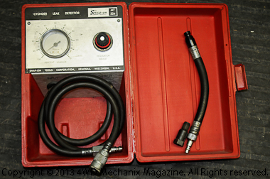
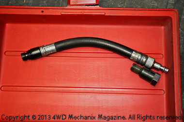
Most engine troubleshooters understand and use a compression gauge to diagnose serious engine seal problems. I use a compression gauge for a quick and general overview of engine condition. In addition to the relatively inexpensive compression gauge, I have used a cylinder leak down tester for over thirty years now. A quality compression gauge is valuable. This gauge has been with me for many years. Ford truck buffs will appreciate the 18mm spark plug thread adapter. Triton aluminum head owners would value the iron FE and big-block heads—with 18mm iron spark plug threads and tapered seat ends—no need for a gasket, a proven Ford approach until the aluminum cylinder head era! (Click on photos to enlarge.) A compression gauge requires a cranking engine to force compression pressure into the gauge. Used properly, the compression gauge reading indicates the PSI (U.S. and British measurement) of gases compressed into the cylinder head's combustion chamber. Basics for using a compression gauge: 1) Disable the ignition to prevent engine startup, 2) hold or block open the throttle during cranking to assure adequate induction air volume for test accuracy, and 3) crank the engine for seconds per cylinder, not for a lengthy period. As the engine cranks, watch for a peak reading at the gauge, which will occur within a few seconds of cranking. A typical automotive or truck engine is designed to crank over at 80-200 rpm to achieve ignition/combustion, so several seconds of cranking is plenty for a compression check! The compression gauge provides a reading of peak compression during cranking, not when the engine fires or is running. Actually, the engine's compression while firing under load may be much lower than the cranking compression. As cylinder pressures rise, like when climbing a grade or pulling a load—or crawling rocks along a 4x4 trail—the ability of the cylinders to seal will be far less if there is engine wear. Note: Engine wear that I'm discussing here is not just worn valves, a head gasket leak or valve lift issues. It's also the cylinder's ability to seal under load, and more specifically, the condition of the cylinder walls, pistons and piston rings. In the case of pinpointing cylinder wall and ring seal, a compression gauge is simply not up for the task! This is my Snap-On cylinder leak down tester, an MT324 model purchased in 1981. Prior to that time, I used a compression gauge and an engine oscilloscope "dynamic compression test" mode to compare relative cylinder condition. The leak down tester provides pinpoint diagnosis! (Click on photos to enlarge.) When we move to the leak down test, our entire aim changes. Instead of cranking compression, we're now addressing one thing: actual cylinder seal. This means consistent valve seal, piston/ring seal, head gasket seal and no casting cracks. The test is not a cranking test. It's static with the piston at top dead center (TDC) of its compression stroke, valves closed. This last point is very important. The leak down test takes compressed air from your air compressor and an air hose source and runs that air into the spark plug hole (plug removed). Typically, a leak down gauge will operate at 60 PSI or higher, enough force to push the piston downward if the piston is not precisely at the peak of its travel: TDC! This is one way to find TDC accurately: a two-stroke engine timing tool, purchased during my motorcycle repair shop days in the early 1970s! Note the spark plug thread adapters with a slotted section in the adapter to aim a dial indicator directly through the spark plug opening. This tool finds TDC within 0.001" accuracy! The setup is time consuming, however. There are other, quicker ways to find TDC for the purpose of a cylinder leak down test—as long as the piston is at its peak and not likely to plunge downward when you apply compressed air! (Click on photos to enlarge.) It takes time to set up a leak down test. On a Jeep engine like JJ_Jeep's 4.0L inline six, there are only two cylinders that can use the crankshaft pulley marks to set TDC: #1 and #6. The other cylinders either require 1) looking into the spark plug hole to align the piston with TDC, 2) use of a two-stroke timing kit or similar fixture and a dial indicator in the spark plug hole to find TDC, or 3) marking the crankshaft pulley accurately for each of the other four cylinders at TDC. Make sure the piston is on the compression stroke's TDC when running a leak down test. Note: A crankshaft pulley 360-degree tape is available from sources like Summit Racing. This can make leak down tests much easier. The firing order helps identify the cylinders, and in the Jeep inline six, the order is 1-5-3-6-2-4, making #1 and #6 pistons reach TDC at the same time. Remember, too, that we're working with four-stroke engines, and the piston must be at TDC on the compression stroke, not the exhaust stroke! If you set the piston to TDC on its compression stroke, each of the valves will be fully seated. Introducing compressed air at this point will fill the combustion chamber and the narrow space around the piston and above the upper piston ring. The air will come in steadily (if you have enough air supply!) at the air system's line pressure that you set. The principle of the leak down test is for the gauges to measure incoming line pressure and also the pressure bleed-off within the cylinder. The bleed or "leak" is read as a percentage of the total air volume filling the combustion chamber, head gasket space, and piston-to-cylinder wall gap above the upper piston ring. Example: Let's say that 100cc of air fills the combustion chamber, head gasket space and the piston to cylinder wall gap above the upper piston ring. If the ring gaps and any other seepage allow 10cc bleed-off of compressed air, the "leak down" in this case is 10%. 8-10% is excellent seal for a production automotive engine with gapped piston rings. Caution: Always make sure the gauge couplings and the fitting at the spark plug hole do not seep air! A leak at the gauge's spark plug fitting seat will throw off the leak down readings. The biggest asset of a leak down test is the very fact that the piston is at TDC. On an internal combustion engine, the wear of cylinders, or "taper", rakes outward toward the top. This means that the widest wear point in the cylinder will be right below the cylinder "ridge". The ridge is created as the taper grows, and the greatest wear point is where the top piston ring stops. By pressurizing the cylinder with the top compression ring and other rings in the tapered zone, there is the highest likelihood of compressed air "leaking" past the piston rings: The ring gaps, especially the top compression ring, are at their widest, and this is a direct cause of leakage. With the piston in this position, the rings lose tension, their gaps are widest, and compressed air leaks by in greater volume. The extent of ring wear or cylinder taper dictate the percentage of leak down. One proof that this phenomenon works: On a worn engine, back off the rocker arms and close both valves. Keep them closed. Raise the piston to TDC (maximum cylinder taper) and check the leak down rate. Now drop the piston to the BDC (bottom dead center) point with the valves closed. The piston is now in a "normal", minimally worn zone of the cylinder wall. There will be a distinction in the degree of seal and the leak down reading, since the ring gaps close up at BDC, the ring tension increases, and the cylinder seal becomes normal or at least closer to normal. If there is little leakage difference, and the leak down percentage is low or minimal at both of these piston positions, cylinder taper is minimal...Without tearing the engine down for inspection, you likely have an engine with minimal cylinder wall and ring wear! Before loosening rocker arms to close valves, run a regular leak down test with nothing but the spark plugs removed. Since JJ_Jeep's issue with the 4.0L is a #1 cylinder misfire, it's easy to set up the leak down tester for the #1 cylinder, using the timing mark on the crankshaft pulley and the timing cover marker to set the crankshaft at TDC. Make sure the ignition is disabled to prevent engine firing...I bring the pulley to the "O"-degree position by slowly turning the crankshaft in its normal direction of rotation. Make sure you're on the compression stroke. If necessary, remove the distributor cap and note the rotor position. (JJ's pre-'99 TJ 4.0L still uses a distributor cap and spark leads.) Coil-on-plug engines are a bit more involved. Make sure the piston is coming up on its compression stroke to exact TDC. Read the tester instructions for recommended air supply pressure. On gapped rings with inside gas ledges on the compression rings, supply pressure will determine the force that the rings will exert against the cylinder wall. A cranking or running engine will typically have 120-175 PSI working compression in each cylinder. The leak down gauge may want much less incoming pressure than this...See the manufacturer's recommendations for your leak down tester. With the valves seated, piston at TDC and air pressure at the tester gauges set properly, we now have a steady stream of compressed air entering the cylinder. Even if the valves and head gasket seal perfectly, a percentage of incoming air will "leak" by or "down" the cylinder and past the rings. This is normal if rings have end gaps, which is the case for most production automotive engines. Note: Overlapping end, interlocking or "zero gap" rings have minute leak down. On a typical production engine, there is a controlled and predictable leakage, optimally around 8% to 10%. Zero-gap rings on racing and performance motorcycle engines can seal as tightly as 2% leak down. We need ring gaps on everyday automotive engines to allow for a wide range of heat cycling, expansion rates and varied operating conditions. So, a reading of 8-10% on a newer engine is great. Up to 20%, even 25%, on an engine with some wear can still function well if the engine also has good cranking compression readings. On an engine with 20%-25% or higher leak, I do run a cranking compression test and make sure there is not excessive oil consumption. Assume that a 20-25% leakage engine has a shorter remaining service life. As with a compression gauge reading, uniform seal per cylinder is desirable under any leak down test. If readings exceed 20% or so, start looking for leakage. You will find leaks readily while running a leak down test. When an intake valve leaks, you will hear air escaping through the throttle body or a carburetor's air horn. For exhaust valve leaks, listen at the tailpipe. For piston ring blow-by, pull the dipstick or oil filler cap, and listen for the air entering the crankcase past the rings. If you have difficulty hearing this air flow at any of these points, use an automotive stethoscope or even a piece of tubing, like rigid electrical conduit, as a sound amplifying device. For accuracy, do not run the test for a long period. Oil will leave the cylinder walls, and the reduced seal will be detectable as a higher leak down percentage. Also, on rare occasions, a valve may have carbon or deposit buildup near its face, and the compressed air dislodges debris. If debris lodges between the valve face and seat, there will be a false leak reading. Note: Such an instance would be an engine with serious carbon or deposit buildup. One way to minimize this risk is to not apply air pressure until the piston is at TDC with the valves completely closed on the compression stroke. Why do we care whether the engine has too much leak down if the compression cranking test with a compression gauge indicates "normal" or factory-recommended cranking compression? There's a big difference, as I've shared. In the case of testing for cylinder taper and piston ring gap issues, the leak down tester pinpoints specific wear at the cylinder walls and even the degree of piston ring wear—yes, a widened ring gap, even with negligible taper on the cylinder, indicates ring face wear, loss of ring tension and poor ring seal. This raises the percentage of cylinder leak down. It does matter that the cylinder seal is within proper leak down specifications. So-called "normal" compression gauge readings do not reveal how the cylinders seal under firing and engine load conditions. There is a rise in cylinder pressures when the engine is under load, like accelerating, pulling a grade or even going through the gears. Cylinder pressures also dictate the amount of spark voltage demanded. Why is a compression gauge inefficient at diagnosing cylinder sealing troubles? Because the real test of engine seal and performance is the ability of rings, valves, gaskets and castings to work under load. Piston compression rings have inside ledges that face upward. Compressed gases fill this void and force the piston ring outward against the cylinder wall for better sealing: The higher the cylinder pressure, the more outward ring pressure. As the piston rises in the cylinder, the ring pressure increases, and that contributes to cylinder taper. As I shared, taper creates a loss of compression due to the widening ring gap and loss of ring tension. Combustion pressure rise creates even more outward force at the compression rings, especially at the cylinder's taper zone. Note: Ring gap is the measureable space between the ring ends, not space between the ring face and the cylinder wall. Unless zero gap type, new rings call for a specific clearance gap in thousandths of an inch or mm, measured with a feeler gauge. As one example of the difference between cranking compression and cylinder leak down testing, I recall the stock, FJ40 "F" engine in the 1971 Land Cruiser that I built into an OFF-ROAD Magazine project in the late 1980s. The engine had considerable mileage, though it consumed minimal oil and ran "okay". A cranking compression test showed adequate and uniform compression over the six inline cylinders. Uniform compression, in particular, is always desirable. When I ran a leak down test on this engine with my Snap-On tester, the results were astounding: While the engine had uniform cranking compression around 120-125 PSI, the leakage per cylinder was 40% or higher! How is this possible? In this case, it had much to do with the incredible integrity of Toyota iron engine block castings, with higher nickel content and the hardness to resist taper. Tearing down the engine for a ring-and-valve job, I found the F-six had worn its top/compression piston rings to the point of razor edges! I had nicks and cuts on my fingers from unsuspectingly handling the pistons and rings during their removal. In this example, there was minimal taper, actually almost none, as I could still see factory honing or "crosshatch" running to the top of the ring travel in each cylinder! The ring gaps and diameters had worn to the point that air could leak past the top rings during a leak down test. The lower oil control rings still kept oil from wicking up the cylinder walls and burning. The result: adequate cranking compression, no oil loss, yet high leakage and poor sealing. The pistons and rings could bluff through a compression test by forcing enough air into the compression gauge during cranking—especially with a long stroke inline six. This could not fool a leak down tester! This engine ran sluggishly, the result of inadequate cylinder seal at the rings. The valves seated, the head casting and head gasket were fine, however, the combustion gases leaked past the rings and into the crankcase. Engines like this have a distinct "blow-by" smell in the crankcase oil. While the PCV system can recycle blow-by gases, the remnant of combustion gases remains in the oil. I have often referred to this odor, notable with the oil filler cap removed and the engine running, as the "smell of death". Summing up, the compression gauge does have its place for quick diagnosis of major engine wear or damage. A valve that will not seat, or is actually "burned" with a piece etched out, will not evade detection in a compression test—nor will a blown head gasket or severely warped/cracked head casting. For that reason, an easy and fast check for severe damage can be done with a compression gauge. The leak down tester is a pinpoint diagnostic tool. This test can detect specific valve leaks and wear like cylinder taper or the widening of ring gaps. It can simulate the engine under running load by continually applying compressed air into the cylinder—at the rate and pressure you select. As an added benefit, you can detect a head gasket or casting crack leak, including leaks between cylinders and leaks into cooling ports, which will force cylinder gases into the cooling system, detectable as bubbles at the radiator. Caution: If you suspect a head gasket or cracked casting leak into the cooling system, the leak down test will raise cooling system/radiator pressure to the extreme. Remove the radiator cap before applying air to the cylinders, and start your air flow at a very low PSI, watching for bubbles in the radiator. Cooling systems normally operate in the 12-18 PSI range, depending upon make and model application! If you suspect leakage into the engine's cooling system, set your leak down tester's air supply pressure accordingly. Warning: Always make sure the engine and coolant have cooled down before running a compression test or cylinder leak down test! There are affordable leak down testers. If you do any amount of engine diagnostic work and want to get a better sense for what's inside an engine, to make an informed decision about its condition, I highly recommend a leak down tester. I still use a quality compression gauge to quickly test an engine for major trouble, often following up with a leak down test on the low pressure cylinder(s). Here is just one example of an affordable leak down tester, I found this in two minutes with a Google Search: http://www.tooltopia.com/otc-tools-5609.aspx?utm_source=pricegrabber&utm_medium=cse&utm_term=OTC5609&utm_campaign=pricegrabber_r1 Your test approach and tools of choice depend upon your needs and objectives. I've owned my Snap-On MT series leak down tester since 1981 and use it when necessary. The current generation of testers from OTC and others are more compact and easy to hook up, and they perform the same functions as my Snap-On tester. (Even Snap-On has simplified its testers for today's market.) There are also compression testers and leak down testers for diesel engine applications. I made this leak down tester adapter in minutes. My Honda XR350R and XR500R four-valve thumpers have deeply recessed spark plugs, tough to reach with a spark plug wrench! I took an old spark plug, knocked out the porcelain electrode, removed and smoothed out the electrode strap end, then cleaned out and brazed the threaded plug shell to a piece of threaded black pipe. The brass "T" fitting provides for an additional gauge, and the air coupler nipple fits my Snap-On MT324 leak down tester. You can make an "air hold tool" in a similar fashion. (Click on photos to enlarge.) If you want a very inexpensive leak down simulator without measuring actual percentage of leak, I've made testers for obscure motorcycle applications with peanut spark plugs and deep plug access. (See the photo above.) In this case, you still run the piston to precise TDC on the compression stroke, with the valves completely closed. You can listen and hunt for air leaks at the common points. For the crankcase, listen at the oil filler opening. For an intake valve leak, listen for air at the throttle body or carburetor air horn. Listen at the exhaust or tailpipe for an exhaust valve leak. For a head gasket leak, try soapy water applied at the head gasket edge, compress air into the cylinder at TDC on the compression stroke, watch for air bubbles. Or for head gasket seepage or a cracked casting into a cooling port, watch the radiator for air bubbles—always using low supply line pressure as I've discussed. The commercially available "air hold tool" is essentially to keep OHV valves closed during valve spring replacement without cylinder head removal. This tool can serve as a leak tester—without gauge readouts for the percentage of leakage. K-D and others have made air hold tools for years if you want a ready made tool. The principle remains for leak testing: Run the piston to exact TDC on its compression stroke and apply compressed air into the cylinder. You can set air pressure at your air system's regulator. Listen for escaping air. While you won't know the volume or percentage that leaks off, you can detect major air leaks quickly. I've made air hold tools as simply as knocking the porcelain and electrode from an old spark plug. Removing the electrode ground strap, I braze an air coupling nipple into the remaining spark plug shell—the threaded metal section. Clean up the piece thoroughly, removing all debris and loose metal, before inserting your new "tool" into the engine's spark plug threads... Trust this helps you make the right tool choice! Moses


-
JJ...I understand your time constraints and family commitments. Family takes precedence...I'll respond to your questions then open a new, follow-up topic about why I recommend the use of a leak down tester compared to a compression gauge...First, your questions and my answers: Q: I suspect cylinder seal may be a problem because of the high mileage. I was hoping 10W-40 might help extend the engine life a bit here? A: Yes, we're attempting to rule out a cylinder seal problem. There are two entirely different ways to look at cylinder seal: 1) adequate spinning compression to produce sufficient combustion, and 2) true cylinder seal that will prevent seepage under load and resist blow-by. 10W-40 instead of 5W-30 will not compensate much for wear; however, it will help alleviate nuisance rear main or timing cover seal seepage (will not stop an actual leak), and it may reduce oil consumption from valve guide, guide seal or ring blow-by issues. The wear we're concerned about in terms of leak down is at the valves, rings and head gasket—and casting leaks in the worst case scenario, like a cracked cylinder head from severe overheating. Q: I suspect valvetrain wear may also be a problem due to high mileage. A: This can be a problem, and we'll get right down to the bottom of that issue in my follow-up topic on the leak down test! If you mean valvetrain wear in terms of valve lift error, valve lift can be measured with a dial indicator at the rocker arms (valve cover removed). You do need proper valve timing and correct valve lift. Valve lift corresponds to the camshaft lobe shape, lifter function, valve/lifter clearance and rocker arm function. Q: Based on the oil pressure gauge in the instrument cluster, oil pressure runs where it has been for 15 years. A: This is a good sign, helpful in terms of bearing life expectancy if you do make other repairs. If pressure did read low, you might want to make major repairs rather than spending money on a patch repair. Avoid the proverbial "good money after bad" scenario... Q: I'll have to check past repair slips, but I think the timing chain and sprockets and water pump were replaced in the last five years. A: That's helpful and would eliminate or reduce the likelihood of having a valve timing problem. Had the valve timing not been set properly, you would have experienced trouble immediately, as the PCM receives both a crankshaft position and camshaft position reading from your TJ 4.0L inline six. If out of sync too much, the PCM would throw a trouble code. Q: I hear and smell exhaust under the hood when the engine is running. The engine used to have the standard ticking of the tappets, but now it makes a putt-putt sound like an old tractor. I'm still running the stock header after all these years, so perhaps it is cracked or maybe the gasket between the header and head has failed? Any reason to believe this would relate to a misfire? A: The sound of an exhaust leak could very well be a cracked OEM header, it's amazing that your header lasted this long if original! Sounds like a leak from the exhaust manifold gasket area or a cracked exhaust manifold/header. This would not be the "cause" of the misfire, however, an exhaust leak near the head is dangerous in terms of valve warp risk. Under extreme conditions, if colder air drafts back into the engine (at the exhaust port or ports) when the engine shuts off, an exhaust valve can warp. Valve warp like this is unlikely, and the leak down test will reveal that kind of problem. (See my leak down tester follow-up topic post.) Q: Adding to my puzzlement is the fact that this engine consumes no measureable amount of oil and has good power. The dipstick reads full even when I'm ready for the 3k-5k oil change. A: Let's not rule out the possibility that the engine is still viable and functions okay! In my follow-up on the leak down test, I will explain how oil consumption does not always occur when there is engine wear. An engine can have oil ring seal without compression ring seal; in the extreme, this can be an engine with inadequate compression or cylinder seal, yet an engine that still resists oil blow-by and oil burning—or "consumption". Keep in mind, JJ, we're simply trying to rule out an engine condition issue, separating engine "long block" problems from vacuum leaks, fuel flow issues and spark misfire. If the basic engine tests okay, the tune-related problems can be sorted out and fixed. Please see the leak down test explanation at my follow-up leak down test post... Moses
-
Hi, Rich…Although I'll always be a CJ buff, I’d suggest a YJ Wrangler. If a six-cylinder, go with a 4.0L inline, 1991-up model. For four-cylinders, the 2.5L is TBI from ’87-’90, multi-point FI from 1991 to 1995. Four-cylinder models tend to be less expensive. You’d have to be sold on the idea, however. If not, the conversion to a six-cylinder requires welding engine mounts and an upgrade of the transmission as well. (See my MIG welding article with illustrations of this conversion in a YJ Wrangler; the same applies to the TJ Wrangler, as each uses a different frame for four- versus six-cylinder engines.) The six-cylinder YJ Wrangler models use a Peugeot ('87-'89) or Aisin AX15 ('89-'95) transmission; four-cylinder models use the Aisin AX5 (lighter duty). I’m okay with the 2.5L four-cylinder for off-road use. In low range, the four works fine off-pavement if the axle gearing is 4.10 (stock) and tires are stock diameter. If you do a lift kit and oversized tires to 33”, you will need 4.56 gears to move a 4-cylinder Wrangler down the road. For each of these reasons, you may be happier with a 1991-95 factory 4.0L six-cylinder model in decent shape. Avoid the '87-'90 4.2L/258 inline six unless you want to restore the carburetion (see my article) or upgrade the induction system to EFI. (This EFI article on MSD Atomic EFI also describes the Mopar MPI and Howell retrofits for the 4.2L inline six.) Even with a six-cylinder model, tire diameter still dictates gearing. Retrofit 4.56 and 4.88 ring-and-pinion sets, front and rear, would be practical for 33” and 35” tires, respectively. Trust this helps. If you do consider a CJ, and they are all carbureted, the 1980-86 would be the best year range, as they use the iron Dana 300 transfer case with helical gears. Like the '87-'90 YJ Wrangler 4.2L, the emission-laden, carbureted 258 six can be a pain for some...I've restored these systems—it can be done. An emission legal 258 EFI conversion package runs from $1400-$2800. (Even the four-cylinder CJs are carbureted through these years.) That’s enough to say, “Pass.” This is now older technology, and nostalgia only plays so far: You get the restoration bills. I would not consider a 1975 or older CJ, unless you want to fully restore a vintage Jeep and have the time and money to do so. Arguably, the later CJ’s Dana 300 transfer case is superior to the NP207 (earlier four-cylinder) and NP/NV231 (later four- and six-cylinder YJ models). Despite that, an NP/NV231 will last plenty long and is typically less costly to rebuild. The light duty NP207 can be another story. Trust this helps, Rich…Happy to carry the conversation further—Welcome to the 4WD Mechanix Magazine 'Tech and Travel' Forums, looking forward to your topic posts! Moses
-
Thanks, GEO YODA, I do want to see that '83 up close!...Post a topic with some pictures or links to Photo Bucket, or wherever you store your photos, you can even put a few right here on the forums—use the "Attach Files" at the Reply Options! We'll do one of the Tierra Del Sol annual runs—or how about your bringing the Toy 4x4 to the Sierra Range or Nevada? The Rubicon Trail is a colossal rock pile these days. (There are bypasses in many of the worst areas.) You'll find Toy 4x4 pickups and FJ40s, Toy-based "buggies" and 4Runners...We'll connect soon, some place! Meanwhile, these forums are a great way to keep the "community" alive and informed. Looking forward to lively discussions, check out the travel forums for ideas on more you can share...You know San Diego County and the Anza Borrego, others would be very interested in your kind of 'wheeling, too! As a member, you can post topics at any category... Moses
-
Hi, JJ, and welcome to the forums! The #1 misfire could be a variety of things. Since you did ask about engine longevity and whether the engine is at the end of its duty cycle, I'll start with a suggestion: Begin with a compression test, or better yet, a cylinder leak down test. Any internal combustion engine needs four things to be "right", I talk about these basics in each of my books. My mantra for basic engine condition: 1) Normal compression or cylinder seal, I prefer a leak down test for this reason. 2) Normal oil pressure and flow, since the bearings and lubricated parts must remain in reliable condition. 3) Normal valve timing, which means the timing chain and sprockets are in good condition. 4) Normal valve lift, which means that the camshaft lobes, lifters and rocker assemblies are in good condition. Once you get past these concerns, any engine problems are either vacuum leaks, "tune" related or engine management (fuel/spark) issues. Your TJ 4.0L engine uses an ignition distributor for the high tension spark delivery alongside an MPI fuel system. The distributor spark timing is fully controlled by the PCM (computer) and its sensor readings. The PCM also controls fuel flow through the injectors. A check light or 'MIL' with a consistent "#1 Cylinder Misfire" could be relative to either fuel flow or the spark at that cylinder. Spark wise, this could be a weak spark lead, worn distributor cap and rotor, the spark plug itself, or engine troubles like low compression or a leaky valve. A misfire can also be fuel related. Poor fuel pressure/supply can be the issue. (See the Mopar EFI comments in the threads from the CJ forum: Mopar EFI Conversion starving for fuel.) The injector for #1 cylinder can be clogged, too. Or, there may be an unrelated device to consider, like the throttle position sensor (TPS) or the oxygen sensor (upstream sensor). Sometimes, these other components will not send their own signal, yet they contribute to something like the #1 misfire. I don't recommend replacing a number of parts randomly, JJ, I'm just calling attention to related trouble spots... After ruling out the overall engine condition, I'd check the fuel pressure at the injector rail. This should be around 49.2 PSI +/- 2 to 5 PSI. That test can be revealing. The #1 spark wire lead should also be tested for ohms-resistance, and spark to the #1 plug should appear consistent. Spark plug and other ignition issues should be ruled out. The #1 injector is more likely to be consistently faulty—not likely to be intermittently faulty. This is still a possibility, though, so don't rule out a defective injector. For additional troubleshooting guidelines, see these two articles at the magazine, covering tune and troubleshooting on Jeep MPI fuel-and-spark management like yours, JJ: http://www.4wdmechanix.com/Jeep-Multi-Point-Injection-Operation-and-Troubleshooting.html http://www.4wdmechanix.com/Jeep-TBI-&-MPI-Advanced-Troubleshooting.html Let the forum community know what you turn up. I'm certain other forum members will benefit from this exchange, JJ, your questions are thoughtful! I'm here for more discussion... Moses
-
Great to see your participation, I've had a strong pull toward Toyota 4x4s since crawling the Rubicon Trail alongside an FJ40 in 1967. The Toyota 4WD trucks and SUVs are tops, maintaining their popularity and high standards to this day...We'll have fun discussing Toyota 4x4s of every kind! Moses
-
1997 XJ Wiring Issues?
Moses Ludel replied to WMCCALL's topic in Jeep® XJ Cherokee, MJ Comanche Pickup and Grand Cherokee
Good tips, XJ4Ever! Enjoy your enthusiasm and loyalty to these XJ beasties! They have their endearing quirks, and the right front cluster switch #56009512AC for our '99 XJ Cherokee 4WD, LHD, four-door is one of them. Mopar OEM retail is very pricey: $274! Best OEM/Mopar price online: $188.60 plus shipping at http://www.factorymoparparts.com/56009512ac.html. Likely a scarcity thing, as this narrows down to the combination power windows, door locks and mirrors options, each interacting with this controller switch...Find the other three door switches readily in the aftermarket, not this one yet, still looking, may, for the fun of it, take the OEM switch apart and attempt a restore, will share the outcome. I did the regulators/motors as an assembly, aftermarket on the right side, OEM Mopar at the driver's side, one install made a how-to article for 4WD Sport Utility Magazine some time back. A heads up on the regulator installs: Be sure to align with the window glass frames properly to provide smooth and square glass movement! Also, make sure the cable assembly is well out of harm's way when the window goes up and down! Use sturdy (I like HD NAPA brand) plastic ties as necessary with the aftermarket assemblies, they often do not come with the Mopar OEM type hold down clips. As you share, the door panel plastic clips are fragile, especially after years of age embrittlement. Great care will help avoid any issues here. I have the special pry tool, they're inexpensive from KD and others...Window lifts are a common XJ wear item, so all of us should be prepared to deal with it! I'm overdue for the instrument cluster wiring TSB fix, bought the inexpensive wire repair "kit" from Mopar some time ago, need time to install it: Accessing the instrument cluster is no picnic! We had the Cherokee parked in the sun recently—let me emphasize, sun of the Nevada high desert variety, very intense, add some elevation and more UV. We generally park in a shaded area. Drove less than two blocks, and the speedo and tach dropped to "0"; this time the 'Air Bag' light paid a visit, it's all related. A bit of cool down, and the gauges began working, no problem since, including the Air Bag light—typical...I will share the fix as a how-to, have photos already of the gauges in the dropped position with the engine running...Many '98-'99 owners (and others?) will value this repair fix! Moses -
Black Rock Desert Memorial Day W/E 2013
Moses Ludel replied to RareCJ8's topic in Places You Have Been...
Got my attention, Mark! If my plated dual-sport is available, what do you think of HD video coverage on the Jarbidge to Gerlach run! Logistics and details can be worked out...What a plan, what great country to cover...GoPro Hero3 with a helmet mic on the cycle, I'm ready! Fall is incredible across the region, I hunted Areas 6 and 7 in the '90s, the Santa Rosas above Hinkey Summit in the early '70s and know the Sheldon Antelope Range, Kings River Valley and the Black Rock. Did Leonard Lake in a jon boat during the early '70s, mounted the boat atop a Kaiser era V-6 Jeepster, traveled with Irving Tonneson, a well driller from Idaho who ran a pump supply business at Carson City. Great areas! Lots of memories from Reese River Valley, Smoky Valley and Monitor Valley...We'll share stories around a campfire, Mark! Moses -
Black Rock Desert Memorial Day W/E 2013
Moses Ludel replied to RareCJ8's topic in Places You Have Been...
On a Memorial Day weekend a few years back, we joined up with Mark and the Reno 4x4 and Hills Angels folks. I have archival scenic photos from that outing. The aspen and Basque ovens make for great photography, panoramic vantages from Granite Peak as well! These club members are great to 'wheel with... High Rock Canyon ranks high on our list of "destination" four-wheeling trips, we travel there with family and "new-to-four-wheeling" friends. I plan to do High Rock soon on a plated, "true dirt" dual-sport motorcycle, in response to growing interest in dirt dual-sport motorcycling. Been dirt biking as well as four-wheeling, both single- and two-track, since high school. I took my first driving test in the family's '64 Jeep CJ-5—48 years ago this week at Carson City, Nevada! The entire State of Nevada had well under a half-million population when we hit the dirt routes between Tonopah and Austin in 1965. The prior year, I attended Nevada Range Camp with the USDA Extension Service, late spring of 1964. We camped at Big Creek, visiting the reservation ranches 40 miles down the isolated Reese River Valley. I caught a 14-inch brook trout in Big Creek, coaxed from beneath a grassy undercut at the four-foot diameter, snow melt pool that formed the head of the tiny desert creek! Many years later, even the powerful steelhead at Oregon's coastal rivers gave no more thrill than that surprisingly feisty brookie at Big Creek! Our family has always liked destination 'wheeling, where the 4x4 is just that: a means for accessing hunting, fishing, historical and mine sites, archaeological sites, anthropological remnants, rock hounding and Nature in general! My first reach into Nevada's mining and Native American history was a half century ago, and our family still calls Nevada "home" today. In addition to the Black Rock/High Rock Area north of Gerlach, Mark and I share an appreciation for Central and Eastern Nevada, as do many avid outdoor Nevadans! I'd like to gather up fellow destination enthusiasts, either four-wheelers or dual-sport motorcyclists, and share some of these spectacular rural, historical and scenic Great Basin adventures! I've done the Rubicon Trail since 1967. Despite the significant "challenges" that each of us has experienced on the Rubicon Trail, my "quintessential experience" was guiding and driving the first Geo Trackers (one stone stock, the other very mildly modified with 29-inch diameter tires) to negotiate the Rubicon Trail. At the time, one of my professional roles was guiding new 4WD truck and SUV media launches for several vehicle manufacturers plus teaching four-wheeling clinics on behalf of Tread Lightly. The Geo Tracker assignment was a "publicity" challenge for Chevrolet in the mid-'90s. We turned the customary 12-16 hour campout with a Jeep CJ or YJ, or a Toyota Land Cruiser FJ40, into a 46-hour marathon! After winching, Hi-Lift jacking and personally driving both vehicles through the roughest stretches and Sluice Boxes, I suspected that any future trip over the Rubicon would be on my Honda XR350R motorcycle! Chevrolet was ecstatic about the outcome and launched a national print media ad campaign from the photos... My field work includes conducting workshops with friends like Bill Burke (Four-Wheeling America) and Cody Lundin (Discovery Channel naturalist and survivalist). Whether competing at a Land Rover Trek or driving a manufacturer's $80K SUV alongside a rock ledge, I keep it real. I've taught fellow journalists (try that some time!), family members (really?) and friends (remaining friends becomes the goal) to appreciate "low environmental impact four-wheeling", getting to remote, difficult places without destroying the natural world in the process...I'm pleased to share these values, assets and my many experiences—here at these forums! Mark and I have 'wheeled together, including an impromptu run over the Gold Lake Trail after transporting kids with disabilities to a Camp Wamp wilderness base at Hawley Lake near Sierra Buttes...Great to see Mark's photos from the Homestead...Trust we'll see his photos and 'photo bucket' links here as well! Moses -
Mopar EFI Conversion Fuel Pump Troubles
Moses Ludel replied to RareCJ8's topic in 1972-86 AMC/Jeep® CJ and Jeepster Models
Mark, I have your photos and fuel supply system in perspective, thanks... As for TIG or welding the "dinner" plate to the top of the Aero tank for reinforcement, you're right about mild steel and corrosion around fuel. Two options here: 1) galvanizing the tank, if possible and practical, after welding the plate in place or 2) have the radiator shop treat the tank with chemical liner for fuel. This coating is a common process that McCarran Radiator at Sparks has done for me on vintage, rare fuel tanks. If you have something going with A-1, ask about coating the inside of the tank. If done properly, this not only seals, it will prevent the corrosion and oxidative rust you have concerns about...TIG the plate in place and cut any holes before cleaning and coating the inside of the tank. Thread Serts do have their place, and they work. Serts would enable making a round reinforcement plate of stainless steel or other non-corrosive material. Enough Serts would hold well around the circumference of your big round plate or a similar non-corrosive plate. You would need to make a sealing gasket of some kind. If you believe the thin tank top would still waver, even with a circle of Thread Serts in place, quality TIG welding would eliminate any risk of buckle, seepage or a loose plate. Keep us posted, Mark! Moses -
Hi, Pete! Doesn't sound promising...Beyond a U-joint, which is a possibility, this sounds more like a differential issue. Since you were on the pavement and in high range of the transfer case, it is very unlikely that the transfer case is involved. I'd jack the rear axle up after safely chocking the front wheels. Try one side up first. With one wheel off the ground, rotate the wheel/tire back and forth while listening for the "bark" or metallic clanging. Concentrate on the differential area and U-joints. Slanting to one wheel off the ground will maximize the play through the differential. Pay close attention to the pinion shaft, pinion flange, U-joints and bearings. You may have a loose pinion flange. With both rear wheels off the ground, you can check the axle shaft bearings, too. Test axle endplay as well. U-joints are inexpensive and easy to replace...The differential or ring-and-pinion would be a bigger job... Let us know what you discover, Pete! Moses
-
Mopar EFI Conversion Fuel Pump Troubles
Moses Ludel replied to RareCJ8's topic in 1972-86 AMC/Jeep® CJ and Jeepster Models
Mark...Understand the priming time, the OEM pump cycle is short, expecting the fuel to flow readily. With a new pump and filter, and a new regulator, this should be less of an issue. As for the pump #52018391P, not sure about the "P", but this is a 1991-95 Jeep YJ Wrangler 4.0L pump that should work with your Mopar EFI conversion. Common Walbro replacement pump pressure can be 45 PSI or so with 21 GPH flow, still adequate for your 4.6L fuel demands. Be careful when ordering, the typical Walbro replacement pump under this number (without the "P") is just that—a pump only. You need the rest of the module assembly to mount the pump in the tank. If you have the in-tank module frame from a 1991-95 Jeep YJ Wrangler, here is a link to the Jeep/Walbro replacement pump at www.fuelpumps.com: http://www.fuelpumps.com/jeep-fuel-pumps-c-48/jeep-wrangler-fuel-pumps-c-48_437/19911995-jeep-wrangler-fuel-pump-6-cyl-40l-s-efi-chrysler-s-5003860aa-ab-5003861aa-ab-52018390-52018391-p-2209.html They also list a '91-'93 4.0L Wrangler pump #4637193 that has higher output (65 psi and 24 GPH): http://www.fuelpumps.com/jeep-fuel-pumps-c-48/jeep-wrangler-fuel-pumps-c-48_437/19911993-jeep-wrangler-fuel-pump-6-cyl-40l-s-efi-chrysler-4637193-p-2211.html Note: Each of these pumps are designed to fit the OEM pump module, they are not fitted at each end with a host nipple—one end only. See the illustrations for details, this may not work if you don't use the OEM module stand. Contact www.fuelpumps.com and see whether they have a universal Walbro that has hose fittings at each end and the flow rate you're looking for, Mark. As long as the pump wiring will match the Mopar EFI kit approach (confirm before buying), that should do it. Share the Mopar EFI kit pump number with them: 1-888-841-8288. For Mark and others interested, I created this Mopar catalog excerpt in PDF download to illustrate the pump module design and OEM part numbers: YJ Fuel Pump Modules.pdf As a footnote, your photos are useful to others, Mark. I see how you’re doing this whole thing, make sure the “dinner plate” mount has a fuel resistant seal! Regular rubber will not work, use fuel-proof O-ring, gasket material or whatever provides a safe, permanent seal. You do not need or want fuel leaks. Avoid sloughing sealant into the tank, sealant can plug up the pickup sock. Summit Racing may have some solutions here. Let us know what works. Consider a “Thread Sert” solution for your plate mount to tank. Below is a PDF download on this product. R&E Fasteners may have them locally at Sparks, may need the installation tool, inquire or look online. Thread Sert eliminates tapping, welding, brazing or distorting the fuel tank surface. Thread Serts.pdf This should all work, I can see where you’re going with it! Get a Walbro/U.S.A. built pump for better reliability. Selecting a Walbro pump is not rocket science. You need a matching wire setup and fitting arrangement...With a spotlessly clean tank and a properly sealing gas cap (a must for your four-wheeling), you can run the Mopar EFI pump successfully. The new pressure regulator will help, too. Moses -
Mopar EFI Conversion Fuel Pump Troubles
Moses Ludel replied to RareCJ8's topic in 1972-86 AMC/Jeep® CJ and Jeepster Models
Hi, Mark...You have been busy! Regarding your photo bucket links, I simply copied and pasted the links from your Email...Below are your photo bucket links and definitions for the shots. I have answered your post questions below these links, so scroll down further: ******************** the temp fix http://s2.photobucket.com/user/RARECJ8/media/homestead2012075_zps8e8b348d.jpg.html pump pulled from tank http://s2.photobucket.com/user/RARECJ8/media/homestead2012096_zps490457d4.jpg.html bottom of pick up sock http://s2.photobucket.com/user/RARECJ8/media/homestead2012097_zpsbf8ce788.jpg.html http://s2.photobucket.com/user/RARECJ8/media/homestead2012103_zpsceb326a8.jpg.html http://s2.photobucket.com/user/RARECJ8/media/homestead2012105_zpsd94e86e4.jpg.html http://s2.photobucket.com/user/RARECJ8/media/homestead2012107_zps0e92b214.jpg.html showing tank with sending unit and pump removed and related openings. http://s2.photobucket.com/user/RARECJ8/media/fueltank2013001-Copy_zpsdbc12f72.jpg.html detail of the round plate covering pump opening and pump assembly http://s2.photobucket.com/user/RARECJ8/media/fueltank2013002-Copy_zps702f873d.jpg.html http://s2.photobucket.com/user/RARECJ8/media/fueltank2013003_zps3a60fd9c.jpg.html gotta find two replacement gaskets like this for each component http://s2.photobucket.com/user/RARECJ8/media/fueltank2013004_zps4bd19bb8.jpg.html [End of Mark's photo links...] **************** Sounds like your recent tune and cold start/warm up problems have been the fuel pump/supply. Your Mopar EFI two-rail system is a prototype '94-'95 YJ Wrangler, and the PCM is looking for 39 PSI during cranking and 31 PSI at an idle after startup. (I talk about that in my earlier reply to this topic, see above replies.) I believe this could also be the cause of your "ping" issue, as the engine has likely been fuel starved for some time...Keep in mind that fuel pressure alone is not enough. You also need fuel volume, which I described earlier. Sounds like your reasons for not using an in-tank Mopar OEM fuel pump module is cost and possible fit issues. Also, you mention tank depth. On that note, one inch off the floor is plenty; if you raise the pickup too high, you will be unable to access a considerable amount of the tank's fuel. You have several Mopar EFI kit remote mount backup pumps (presumed to be 70-90 PSI and 36-40 gph flow according to HESCO). Why not do like off-road racers: Mount a gang of these pumps, two or three, whatever you prefer. You could run permanent fuel lines and electrical wiring to this fuel supply "system". Using a switching system, you'd be able to quickly switch over, even on the fly, from one pump to another! You can use manual switches with relays if desired, each circuit fused for electrical safety and integrity. The pump activation signal would be the PCM wire lead that currently feeds your Mopar remote pump. You'd want to wire the switching so that only one pump would activate at a time. Although there is some discussion about vibration and steel lines causing cavitation, I don't believe you will experience that kind of trouble with a two-rail EFI system. There is always fuel flowing back to the tank with a two-rail EFI system, and vapor lock is virtually impossible with this arrangement. I have run steel lines along the frame rails (see my magazine article for some details), using EFI grade hose and fittings at the flexing points: the tank-to-frame section and the frame to engine connection at the front of the vehicle. Steel double-flare lines, high pressure EFI hose with EFI rated fittings plus EFI clamps work well with two-rail EFI. Double-flare steel pipe with flare nut ends is commonly sold for both fuel and brake use, brake being much higher pressure needs than fuel. Confirm that the line you're buying is acceptable for both, as fuel can be corrosive. Your idea about quick couplers for fuel is feasible. Check with Summit Racing and the many racing fuel line suppliers. You will likely find a source for high pressure EFI hose with garter spring or clip spring couplers—similar to OEM fuel grade hoses. You would need to carry the special tool for releasing these couplers! Don't lose the tool on a trail... If you have access to a new OEM fuel regulator, try it. You're running a gauge to confirm pressures in any case. Find a permanent and safe gauge mount, and be very careful, there is gasoline under high pressure and volume running to that gauge! Make sure the gauge is designed for ongoing use. As for a plate at the tub floor above an in-tank fuel pump, you're right. Stainless cannot be welded to the tub sheet metal, and you do need an anti-corrosive approach here. Again, I would consider mounting remote (not an in-tank) pump(s) and filters at a more accessible yet protected location. A custom steel skid plate or box enclosure might work. You have options based upon your choice of the pump and filter location. Make sure the filters are rated for the kind of pressure involved. If the Mopar EFI conversion kit called for mounting the filter(s) before the pump, do so. If designed for placement between the pump and the EFI system, do so. There is a big difference, however. The suction side pull will generally not damage a filter. However, high pressure on the push side of the pump can damage a filter if not designed specifically for this usage! If you hit the wall on pump or filter options, the Summit Racing outlet at Sparks is nearby. They likely sell the aftermarket fuel pump that came with the Mopar EFI kit. If so, Summit would have recommendations about filtration and where to mount the filters. Remote fuel pumps of this design need to be somewhat close to the fuel pickup point at the tank. That may dictate a certain location for your pumps. There is nothing inherently wrong with these aftermarket pumps, although the new Mopar in-tank module would provide the kind of service expected from a stock YJ Wrangler or XJ Cherokee...Since you don't need an OEM pump module for your tank fuel gauge sender, the remote mount, aftermarket pump would be that much more appealing. I'm here to continue the dialogue, Mark...Many will benefit from your questions and solutions. Moses -
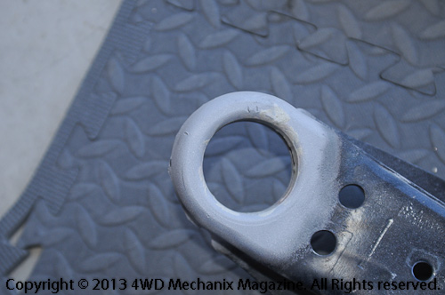
I posted a topic at the welding and metal fabrication forum on one way to restore a bore in a stamped steel piece: "Weld Mold 26-C 'How-to' Oxy-Acetylene Repair: Restoring a Stretched Bore in Stamped Steel". In that 'how-to', I mention heat treated metals and also refer forum members to one of the magazine's slideshow video presentations. The slideshow discusses a major concern when welding, brazing or silver brazing (hard silver soldering) near heat treated parts. Many automotive parts, especially wear points like gear teeth, shafts, splines, thrust washers and running surfaces, have been heat treated to the depth and hardness required. When we weld near any heat treated alloy metals or forged parts, there is always concern about damaging the heat treatment. Even the use of specialized, hard alloy filler materials (some as high as 140K or more tensile in the weld) will not prevent problems at the nearby heat treated areas. If you raise metal temperature high enough during the welding process, any through- or case-hardening will be lost. This means that the metal will soften and be rendered either unsafe or no longer capable of handling its intended function, especially wear points like splines, gear teeth, shafts or thrusts. It is absolutely certain that adjacent to a metal fusion weld, any heat treatment or case hardening will be lost. If parts like a gear or shaft are heat treated or "case hardened" and need welding, you must first "normalize" the metal. This is similar to annealing, but is intended to simply reduce the hardness in the case area, typically the surface 0.030"-0.040" zone if we're talking about common automotive transmission gears and shafts. A ring-and-pinion gear set, due to the size of the gear, is often much deeper case hardening, and some components, especially hardware and fasteners, even get "through-hardened" as opposed to case hardened. Once normalized, a gear or shaft can be welded with an appropriate filler that matches the base metal material. If the match is correct, the part can be machined before re-heat treatment, then heat treated to the component's original Rockwell hardness (prior to normalizing) and case hardening depth if dealing with a case hardened piece. For selecting niche filler materials on alloys and exotic metals, I turn to Weld Mold Company. One way to know the original hardness is a Rockwell C test before normalizing. Determine the depth of case hardening and adjust the final heat treatment accordingly. In the magazine slideshow video, I show and talk about an 8620 cluster gear repair process. There is much more to say about metal prepping, niche welding filler materials and heat treatment...Looking forward to a dialogue in this subject area, we're just beginning! If you have questions, please share. Moses
-
I just completed a shop project worth sharing. An older suspension arm made of stamped steel (mid-'50s vintage) had a ball-joint bore issue. The lower ball-joint was originally a thread-in style—classic Mopar with torsion bar suspension, and the replacement ball-joint is a press-in type. These ball-joints are at the loaded arm, so press-in can work well if the fit is correct. The upper arm uses a threaded, OEM style replacement joint. The lower arms had the ball-joints replaced years ago, and the method called for pressing new, unthreaded ball-joints into the original control arm threads. This being the second time around for press-in joints, the new ball-joints would not fit as tightly as desirable. These control arms are essentially obsolete parts. Otherwise, a new arm would be an option. As a hard rule, we never apply heat to automotive parts or steering linkage, especially parts that have been heat treated—like steering linkage, axle shafts, splines, shafts or gears. In this case, however, the control arm is simply stamped from a heavy sheet of "mild" or cold rolled steel, and the OEM/factory commonly welds attachments to these kinds of parts. (See the rather crude welds at the last photo, these are original, 1950s era welds, a plate welded to the control arm—at the factory!) There were several options, including TIG weld "facing" or build-up and other welding processes. The approach that made the best sense for restoring the bore size at the flattened "threads" was the use of oxygen-acetylene process (a torch and correct tip) to flow a thin, even layer of Weld Mold Company's 26-C alloy flux-coat rod atop the remnant threads. (Click on each photo to enlarge for viewing.)—Moses This alloy rod has exceptional properties, as noted in the Weld Mold Company's description: Weld Mold® 26-C "A flux-coated alloy with super capillary action and thin flowing characteristics. Produces extraordinary tensile and shear strength. Deep penetration of the grain boundaries on the surface of the base metal without fusion permits application with a minimum of heat and distortion." Specification: AWS-BCuZn-A [Properties] Available forms: Oxy-Acetylene The oxy-acetylene process for 26-C, essentially like "brazing", applies much less heat than fusion welding; this is desirable for minimizing risk of distortion and heat affect. Reduced heat and allowing a still air cool down (at 80-degree F ambient temperature) helped protect the base metal. Application was simple. Prep work included glass beading and thorough cleaning. I then heated the thread area, much like brazing, and worked the oxygen-acetylene torch and flux to produce a smooth, strong alloy layer with exceptional penetration of grain boundaries. I kept the flow to a thin, uniform layer...Note that 26-C is high tensile stuff and requires burr grinding to reduce high spots, so keep the layer uniform and at the desired thickness! The result is a strong layer that will behave like higher tensile metal, much stronger than the original stamped steel! Very strong in place plus shear resistant, Weld Mold 26-C flux coat rod requires only normal oxygen-acetylene, brazing-type application process: 26-C Technical Data from Weld Mold Company: Available Processes: Coated Oxyacetylene rod Hardness: 120-160 BHN Tensile Strength: Up to 100,000 psi Bonding Temperature: 1600° F Class: RBCuZn-D Weld Mold Company serves industry and the tool and die shops, types of welding and brazing that require precise, predictable outcomes. Niche products like 26-C target specific tensile strength, shear resistance and chemical properties found in expensive tooling repairs. For alloyed steel and metals, the Weld Mold Company specialty, selective niche filler materials are available to match base metals precisely—even allowing for the re-heat treatment of the piece where necessary—using the exact method of the base metal! (See my comments in the metallurgy post on annealing and "normalizing" metals before making repairs or fabricating components.) I have relied upon Weld Mold Company products for years, and we are proud to have Weld Mold Company as a sponsor at the magazine! The precise metallurgy in Weld Mold Company products, for both welding processes and brazing, has made many of us more aware weldors and raised our interest in chemistry and metallurgy, the science of metals. Better yet, Weld Mold Company takes the guesswork out of selecting the right filler materials for a given job—see the Weld Mold catalog! Note: At the magazine site, there are a variety of projects that illustrate my use of Weld Mold Company fillers. See the Adobe Flash Player video slideshow about gear tooth restoration from my presentation on repairing an obsolete T85N transmission cluster gear. The gear was originally cast from 8620-type alloy metal, machined and then case hardened. (I discuss metallurgy and heat treating needs here, too.) The narrated slideshow presentation includes a transmission iron casting repair as well. This presentation is one segment from my guest speaker role at the 2011 Midwest Willys Reunion. I also discussed a large cast iron axle housing repair done with TIG process. That video slideshow is available at the magazine, too. Click here to access the iron tractor axle repair slideshow in Flash video, which you can view using free Adobe Flash Player... These kinds of restorative repairs begin with choosing precise, niche Weld Mold Company filler metal products! Coupling Weld Mold Company welding filler materials with the stability and performance of a machine like the HTP America Invertig 221 TIG and arc welder produces phenomenal results... Whether you're a 4x4 shop owner, a machine or tool-and-die shop, or a serious metal fabricator of off-road vehicles, Ultra4s, dirt motorcycles or OHVs, get to know the folks at Weld Mold Company—learn about metallurgy and go up the metal fusion and brazing learning curve! Moses


-
1997 XJ Wiring Issues?
Moses Ludel replied to WMCCALL's topic in Jeep® XJ Cherokee, MJ Comanche Pickup and Grand Cherokee
This is a wonderful posting, XJ4Ever! The right side power switch is currently defective on our '99 XJ Cherokee Sport 4-door, and this means the right window will not go down, the remote power door lock key fob will not activate the power locks, and the passenger has lost control of all switch functions. The wiring schematics are different for the two-door models and so are the symptoms for the switch failures. I need to get after that switch, I've already done the window lift motors and cable assemblies...both driver and passenger front. The comment about factory routing of wires at the headliner may save many from doing the same—who would think! They need to make wiring schematics three-dimensional. The battery issue is a regular, as the wiring corrodes badly at the battery terminals and outward as you describe. Also, acid and debris build up at the battery hold-downs. You raise a very good point about not only voltage tests but, I would add, tests for resistance and voltage drop. Load tests by lamp-load method or a voltage drop test over distance would be smart. As we know, the XJ Cherokee is a remarkable utility vehicle. They run seemingly forever with routine service. Their quirks are known, as are the fixes, and we learn to live with the nuisances. All things considered, the XJ Cherokee puts the "Volkswagen Beetle" (air-cooled engine era) myth to rest. Not only do we have the 4WD option, but the XJ will run to 300-plus thousand miles on the original axles and powertrain! The Beetle, despite all the hype and nostalgia, seldom saw 80-100,000 miles without a valve job, cylinder and piston replacement, a new clutch or two, suspension parts, replacement of all the control cables and a new exhaust system. Credit to AMC for this remarkable, bold initiative, a compact SUV, likely the most durable production vehicle in history—especially outside the Rust Belt! With a unitized body that convinced us all, Dana beam axles front and rear, durable two-speed compact truck transfer cases, excellent transmission choices, plus a bulletproof inline six with seven main bearings and EFI from 1987-on, AMC/Jeep and Chrysler hit the mark! The TBI 2.5L four, from day one in 1984, left an indelible impression, replaced in 1991 by the more efficient 2.5L Chrysler MPI engine...For those with an '84-'86 V-6 Cherokee or '86 V-6 Comanche pickup, the breakage prone G.M. 2.8L V-6 crankshaft and chronic rear main seal leaks can be eliminated with a G.M. direct replacement 3.4L V-6 RWD crate engine. Has anyone gone this route? Anyone tried a 302/5.0L Ford V-8 in an XJ? Thanks for joining the discussion XJ4Ever, your post is a delight, and we look forward to more! Moses -
Mopar EFI Conversion Fuel Pump Troubles
Moses Ludel replied to RareCJ8's topic in 1972-86 AMC/Jeep® CJ and Jeepster Models
Interesting trip to a favorite haunt, the Black Rock/High Rock country!...Some background on Mark's CJ-8, this vehicle has been featured at the magazine in HD videos with its Hewes Performance built 4.6L stroker six. Mark had a Mopar EFI Conversion on the original 4.2L inline six, and he moved that equipment over to a fresh 4.6L stroker long block. (Click on the link to enjoy the HD videos detailing Mark's engine and the CJ-8!) Just prior to the start of the forums, Mark and I talked about tuning issues, and there was a hint of fuel supply troubles from his symptoms...The engine uses the PCM that comes with the two-rail (1995 4.0L prototype) Mopar EFI/MPI system. The only modification to his engine is the use of Ford 5.0L V-8 injectors, discussed at the magazine site, to accommodate the added cubic inches of a stroker motor. Mark, sounds like there is a lot of debris in the fuel tank, and your plans to flush the tank are wise. Having quick access to the fuel pump is a good idea, too. As for the two-rail versus single-rail EFI, you are fine with the two-rail as long as the return flow is unrestricted and the fuel regulator at the injector fuel rail works properly. The "normal" pressure for your Mopar EFI, which is essentially 1995 Jeep Wrangler 4.0L off-the-shelf parts, is 31 PSI when running at an idle and approximately 39-41 PSI during cold start cranking. Your low fuel pressure from the pump could explain the recent cold start troubles, as you were not able to muster the factory 39-plus PSI during the cranking mode. See my fuel pressure and tuning details at the magazine for specifications: http://www.4wdmechanix.com/Jeep-Fuel-Pressure-Requirements.html [see details and my pointers on use of the right hose types and clamps for this EFI system.] http://www.4wdmechanix.com/How-to-Tuning-the-Fuel-Injected-Jeep-Inline-Six-Stroker-Motor.html [i just added some updated tuning information at this URL page...Also see my recent forum topic posting on "Jeep 4.6L Stroker Inline Six Camshaft Choices and Tuning".] Again, the stock 1991-95 4.0L two-rail EFI/MPI engines operate at 39-41 psi during cranking and 31 psi with manifold vacuum applied at the pressure regulator. If you're now experiencing 41 PSI going down the road, and if the stock pressure regulator at the rail is not defective, make sure the vacuum hose to the fuel pressure regulator (at the rail) is attached to the correct vacuum source and pulling vacuum properly. Connected, the vacuum line at the pressure regulator should keep an idling engine at 31 PSI, read at the fuel rail test port. Disconnect the vacuum hose from the regulator with the engine at an idle: The rail test port pressure should bump up to 39-plus PSI. An adjustable regulator is available from HESCO for fine tuning if necessary. The Ford 302 V-8 injectors (F1TE-D5A) flow 24.25-pound/hour @ 39.15 PSI, which is why this is the optimal injector for a two-rail Mopar EFI system on a stroker inline six. You get true 24-pound/hour flow availability, which works well for the stroker buildup of a 4.0L into a 4.6L! So, Mark, you have the right injectors, and the pressure you're currently getting sounds like a close match for the Ford injectors. Your fuel supply pressure, regulator pressure and injector flow rate should each work with the Mopar EFI Conversion's PCM. If you run the correct pump pressure and volume, regulator setting and injectors, using the right hose and fitting types, clamps and so forth, you'll be fine. Starting should get easier with a new pump. As for pump pressure and volume, the supply pump that came with the Mopar system is typically 70-90 PSI rated with around 36-40 GPH flow rate. Again, the excess pressure returns to the tank on this two-rail system. (Make sure there are no restrictions on the supply or return side lines!) HESCO sells this pump as do many others, it is a common aftermarket design that simply provides enough pressure and volume to "over-supply" the system. The key is the pressure regulator, which directs the excess pressure/flow volume back to the tank. Be aware that the PCM controls fuel flow on this system. Don't get creative and route a wire from the ignition hot lead directly to the pump. You must use the wiring and relays supplied with the Mopar EFI kit, as this emulates the stock 1995 Jeep Wrangler 60-way PCM functions. If necessary, revisit the wiring schematic that came with the Mopar EFI kit to assure that the fuel supply gets triggered by the PCM—which is not simply a "key-on"/"key-off" fuel pump. The PCM controlled fuel supply is for safety and performance. I have several articles at the magazine relating to installation of a Mopar EFI kit, both the two-rail and the later single-rail types. As for single- versus two-rail differences, the single-rail design uses higher rail pressures (see my article links), adjusted by a regulator atop the fuel pump module at the fuel tank. Mopar Performance's later EFI conversion kit supplies this regulator, modified to fit in-line on the fuel supply system. If you run a single rail system's higher rail pressures, you need different injectors to get precise 24-pound/hour flow. Your current injectors with the additional pressure could over-fuel the engine, producing 27 or so pounds/hour flow at the single rail's potential 50-plus PSI pressure. Since you already have these injectors and a two-rail system, I would stick with it. There is no inherent problem with the two-rail design. You can mount the replacement fuel filter as shown in the EFI kit's instructions or as seen at my magazine articles on the EFI conversion. Making a hole in the tub floor is not a bad idea, although you need enough room to remove the hoses from the pump and safely handle the wiring. As a result, this would not be a small hole, as you would need to get your hands and tools in there. For an alternative, consider relocating the pump to a safe, outside frame rail mounting point near the tank. Readily accessible from the side of the vehicle and out of harm's way, guarded with a custom skid and brush plate if necessary, this could be a solution...Share your thoughts, Mark... As a footnote, the fuel filter can clog readily. Make sure the fuel cap seals from dust on those alkaline roads and the Rubicon Trail! Change the fuel filter regularly, and carry a spare...Get that tank flushed and check the tank pickup for debris as well. Great to have you posting at the forums! Moses