Moses Ludel
-
Posts
4,447 -
Joined
-
Last visited
Content Type
Profiles
Forums
Blogs
Store
Articles
Gallery
Everything posted by Moses Ludel
-
 There's a loyal following for many of the "adventure-touring" motorcycles, cycles like the KTM 990 Adventure or BMW F800GS and 1200GS. On the other hand, many dirt bike riders are now turning to "plated" dirt bikes, bridging the gap between asphalt and a desert enduro bike. Do we need to draw a literal "line in the sand" about what makes a legitimate off-pavement motorcycle? I have ridden this '84 XR350R for nearly two decades and also own an '84 XR500R. Despite growing parts availability issues, these bikes are failsafe mounts for open desert riding. For the magazine's 2012 King of the Hammers coverage, I took the XR350R to Johnson Valley. A dual-sport conversion for plating this cycle has been considered, if so, highway riding would be limited. I would not hesitate to take this machine over the Rubicon Trail and often ride to remote desert and mountain reaches! For decades, I have ridden dirt bikes (primarily Honda XRs) in single track woods and open desert. I have ridden on asphalt for over half a century, beginning with motorcycles like a vintage BSA 650 Lightning, a Victor 441 and a Rocket III 750. More recently, my highway cycles were an older BMW 80GS boxer, a Honda GL1500 Goldwing and a BMW Kll00LT. Despite my respect for high end adventure touring motorcycles like the KTM 990 Adventure, I have an opinion and will share it: Serious dirt bike riding requires a true dirt bike—adventure-touring bikes, even the best of them, are no match for a true enduro motorcycle off the pavement... KTM, Yamaha, Honda, the Christini AWD DS and others now offer serious dirt motorcycles that meet DOT and EPA highway requirements for street legal use. (I do not include Kawasaki's KLR among "lightweight" dirt plated bikes, as the beloved KLR650 has crept from 325 pounds to a porky 432 pounds in recent years!) As an open desert and single track woods rider, I am drawn to these bikes. Unless a lot of asphalt is in the plan, I believe a true dirt bike with D.O.T. approved knobby tires is the best mount for serious off-pavement use—and moderate distance road riding... Contemporary dirt motorcycles with minimalist D.O.T. equipment weigh under 300 pounds. An adventure touring beast can run over 500 pounds, in particular a road-ready machine like the BMW 1200GS. While I truly appreciate the handling, safety and highway agility of a BMW motorcycle, jerking a 525-plus pound motorcycle out of a sand trap is not my idea of a good time...For those who do think of this as an "adventure", I heartily recommend Warn Industries' new line of portable winches designed for adventure touring motorcycles. Admittedly, the plated dirt bikes are minimalist and intended that way: A KTM 500 EXC tips the scale around 250 pounds...These machines remain true enduro motorcycles. Slightly higher in weight is the AWD Christini, coming in at 288 pounds with two-wheel drive traction, a worthy trade-off and ready solution for those sand traps! Before adventure touring motorcycle aficionados boycott this forum, let me add that I have owned a BMW 80GS and a BMW K1100LT. Each was terrific—on the highway. "In the day", I owned BSA motorcycles, including a 441cc Victor, and despite the Victor's lighter weight, it was a stodgy motorcycle off-pavement. Today's dirt motorcycles would run circles around a Victor—or any other vintage "enduro" or "scrambler" motorcycle with vertical rear shock-coil springs! So, I'm raising these questions: 1) Is there a place for adventure touring motorcycles off-pavement? 2) Can a rider on a lightweight dual-sport with DOT knobby tires survive much time on the asphalt—if so, how much? What are your views on each motorcycle design?...Join this forum and share your off-pavement experiences and preferences! Moses
-
At the magazine, building a Jeep inline 4.0L six with a 4.2L crankshaft (stroker motor) is very popular. Tony Hewes (Hewes Performance, Reno, Nevada) and I did a series of HD videos and shared our favorite components for a 4.6L (0.030" overbore with the 4.2L crankshaft) stroker motor build for combined street and trail use. Since then, we have received a lot of feedback and continue to address the tuning and camshaft requirements of these engines. From our testing, the pre-coil pack (1998 TJ and older 4.0L) engines with older style injectors do very well with Ford 5.0L V-8 24-pound injectors—no emission quirks, "Engine Check" lights or other issues when tuned correctly. Ford part number F1TE-D5A or Bosch number 280 150 947 is the specific injector type. These engines work well with the 252H CompCams grind camshaft and 8.7:1 compression. Later, 1999-up TJ Wrangler and 2000-2001 Cherokee engines with coil-pack ignition have square injector connector plugs. For these engines, stroker builders use the Dodge Ram 5.9L V-8 injectors listed for 2000-up with coil pack. This is the injector that HESCO calls a "24-pound/hour”. HESCO supplies rebuilt GB injectors, although new Mopar OEM part numbers are available. This injector also crosses over to the aftermarket Bosch Fuel Injector #62005 offered at Summit Racing for a significant price per injector. Here is the GB website: http://www.gbreman.com/index.html. The 5.9L Ram truck V-8 application is the GB812-12132 injectors for engines to 2003. I researched further and came up with the OEM 5.9L Mopar V-8 injector part number: 53031740AA. (I used 2001 as a clear year for coil-pack and square injector plug.) This OEM Mopar injector is 23.61 pound/hour rated at 43.5 PSI. This is a "high impedance" injector design with a square plug socket. The OEM injector on a coil-pack engine rates 22.5 pounds/hour at 49.0 PSI fuel pressure, which may work okay on a coil pack stroker engine unless the cylinder head, compression or camshaft/head combination is an issue for the PCM. Fuel rail pressure of 49.2 +/- 2 PSI should be confirmed by factory testing method. Fuel Rail Pressure Test.pdf This PDF is instructional for running fuel rail pressure tests on Jeep MPI. This is the 1997-up XJ Cherokee and TJ Wrangler type with fuel tank mounted pressure regulator and single-rail injection. In the late '90s, my engineer friends, Jeep performance enthusiasts at Mopar, were talking about 5.9L Mopar V-8 injectors for 4.0L/4.6L stroker engine builds. This has apparently been a route to go, with a 24-pound/hour injector rating. I researched the Jeep ZJ Grand Cherokee 5.2L/5.9L V-8 injectors from the mid-‘90s: 1995 Jeep 5.2 ZJ/Dodge 5.9L V-8 injectors are Part #53030262 and rated to flow 24.6-pound/hour at 39 PSI. By 1996, the Jeep V-8 injectors rated 23.2 pounds at 49 PSI. The 1995 Mopar injectors (24.6#/hour @ 39 PSI) could be an alternative to the 302 Ford injectors for a stroker build in a 1991-95 Jeep 4.0L MPI chassis application if the engine demands that kind of flow. Summing it up, if GB is accurate, using the right injector cores and parts for this application, HESCO is marketing a “24-pound/hour @ 43.5 PSI injector for a stroker inline six. A caution here is that the '97-up Jeep TJ Wrangler and XJ Cherokee have a 49.2 +/- 5 PSI rail pressure. Flow could be higher than 24 pounds/hour at this 49.2 +/- 5 PSI rail pressure. If the GB812-12132 injector is okay for a coil pack later engine with the later cylinder head casting, the GB812-12132 square plug injector would be the choice for later coil-pack engines. There are a number of sources for these GB injectors. We're still testing the CompCams 252H camshaft in a later 4.0L (1999-up TJ Wrangler/2000-up XJ Cherokee) engine with the redesigned head and coil pack ignition. Tony and I will update on these late 4.0L/stroker engines. The pre-'99 stroker engines and stock PCMs have worked well with this camshaft grind. We're consulting with CompCams about a possible new grind for later coil-pack ignition stroker engines. The 1997-up TJ Wrangler and Cherokees with the tank-mounted fuel regulator use higher fuel pump/line pressure. I would stick with Mopar 53030262 or Ford 302 V-8 type injectors* on the 1997-98 TJ Wranglers and Cherokees through 1999 (without the coil pack system). *Footnote: 24-pound 302 5.0L V-8 injectors fit the pre-coil pack engines; coil pack engine injectors have a square plug connector. Below are some useful links and comments at the magazine site: http://www.4wdmechanix.com/Jeep-Fuel-Pressure-Requirements.html [i detail pressure ratings and designs for Jeep engines equipped with MPI/EFI. 1997-up single rail systems with tank-mounted pressure regulator are higher pressure, running rail/injector pressures typically around 49.2 PSI +/- 2 PSI. This includes the coil pack engines with square wire plug injectors.] http://www.4wdmechanix.com/YJ-&-TJ-Jeep-Stroker-Six-Upgrade.html http://www.4wdmechanix.com/Jeep-TBI-&-MPI-Advanced-Troubleshooting.html [Overview of OEM tuning methods and factory diagnostic tools required.] http://www.4wdmechanix.com/Vlog-Why-Build-a-Jeep-4.6L-Stroker-Inline-Six.html [Video vlog comments.] http://www.4wdmechanix.com/How-to-Tuning-the-Fuel-Injected-Jeep-Inline-Six-Stroker-Motor.html http://users.erols.com/srweiss/tableifc.htm [A useful third-party website for every popular OEM fuel injector’s flow ratings.] http://www.4wdmechanix.com/Vlog-Road-Testing-Jeep-4.6L-Stroker-Inline-Six.html [My video comments on Brent H.’s Cherokee 4.6L build and its drivability. This is a video vlog plus a list of key components used in this Hewes Performance buildup for a 1998 Jeep XJ Cherokee chassis.] Of course, there’s also the entire 4.6L Tony Hewes interview series of HD videos, six individual videos covering the build of a stroker inline six-cylinder Jeep engine! Moses
-
Another pre-forum, Q&A exchange with Jason Logan (forum member JayDLogan) is useful to those installing a new clutch. Jason has concerns about which type of release bearing to use. The discussion continues here at the forum:: Jason: Hello Moses! Hope I am not bombarding you with questions? I have sent to you a photo of two release bearings for my 1999 jeep 4.0L clutch assembly. Both are brand new. Which release bearing should I use? The one on the left is a composite (plastic)/steel design while the other one on the right is full cast (original design) . Thanks for any information you can give me! Luk is at left; OEM iron casting is at right. Click on photo to enlarge. Moses: Both release bearings work and appear to fit the same way, right? I’m drawn to the cast item at right in the photo you sent. Unless there is interference or a stack height problem, either should work. Match-up to the OEM would be advisable…The composite looks like a possible weight savings and maybe an NVH (noise-vibration-harshness) update. Jason: The composite/ plastic bearing came with the Luk Pro Gold clutch kit. I was apprehensive to use this new bearing because of its construction. I talked to Luk technical department and they said that the composite would not hang up on the bearing retainer if there was any signs of wear. They also told me that it does not require grease at the bearing retainer friction points. The cast release bearing is from mopar and I think I am going to install that one since it is a direct replacement from the original. I thought I would ask you to see if there was a better version of the original! Thanks again! Moses: I understand Luk’s approach, and that may be a perfectly good design—and improvement. It’s not earthshattering either way, as each design has its merits…There is a larger concern with the TJ Wrangler clutch assembly and release bearing selection: stack height of the clutch and bearing. The master cylinder for the clutch has only so much travel, and the location of the slave cylinder determines the amount of clutch release travel. These clutches are "self adjusting", and the release bearing and arm must be positioned correctly to allow full clutch travel and compensate for disk wear over time. Concerns include the flywheel face (resurfacing the flywheel affects the stack height relationship to the bellhousing); the clutch disk thickness and pressure plate height; and the release bearing's yoke flanges-to-bearing face height. The Luk and OEM bearings appear to have the same flange heights, and that would be my bigger concern...Moses
-
Sooner or later, every AMC/Jeep inline six cylinder engine will require a rear main seal replacement. Forum member JayDLogan and I had this Q&A exchange just prior to the start of the forums. This should benefit others and will continue here at the forum: Jason: I am installing a new rear main seal in my 1999 jeep wrangler 4.0L. I am a bit confused on where to put the sealant. I have attached a few photos. I am using mopar anaerobic sealant, is this correct? The sealant should not be on the bearing cap mating surfaces, right? My understanding is to use sealant along the full length of the chamfered edges, on both ends of the bearing cap. In addition, apply sealant to the upper and lower tabs on the lower rear main seal. The factory manual is very vague. Some sources say not to put sealant on the upper and lower tabs of the lower seal or any sealant in seal seat in the bearing cap. I am concerned that if I put sealant on the seal tabs, that it will prevent a proper seal. Can you clarify what is required and what NOT to seal with a detailed diagram or picture if possible? Also, is it wise to replace the oil pump and pick up tube while I am doing the rear main seal? The jeep wrangler is a 1999 with approximately 120km on it! Photo at left is definitely wrong use of sealant. Second photo with anaerobic sealant looks slightly better but still needs sealant at chamfer edges. Do not apply sealant at the seal's lips! Cap would need installation with this sealant still pliant...See the comments and details below... Moses: Jason, see the attached PDF scan below. This is the official Mopar procedure. My rules-of-thumb are to 1) avoid creating a gap between the cap and block from using too much sealant, and 2) use sealant wherever oil can “wick out” between the cap and block. The illustration is very helpful. A sealant bead at each cap chamfer to the block is required. You do not want an oil leak or seepage between the cap and block. 4.0L Rear Main Seal Installation.pdf As long as the residual film of sealant will flatten and not interfere with cap torque and mate-up of the cap to block, you’re fine. Note that Loctite 518 is the recommended sealant…The seal and tabs are of oil-resistant material that seals well on a clean surface. These materials even swell slightly in the presence of oil. There’s no need to use excessive sealant. Follow the Mopar recommendation for these modern sealing materials…Presumably you’re using the one-piece oil pan gasket, which works very well and is way easier to install than the old 4-piece sets! AMC/Jeep oil pumps put out high pressure and volume. Unless you have experienced low or erratic oil pressure, your pump is likely fine until you completely rebuild the engine. Most often, the damage to oil pumps is from debris, not “wear”, as the hard steel impellers run in a constant oil flow, which prevents rapid pump wear. If the engine has sludge and the pickup screen appears clogged and suspect, I would replace both the pump and oil screen assembly. I use a Melling high-volume replacement pump. Jason: So are you saying to only put sealant on the chamfer edges of the bearing cap (metal surface)? Should I put sealant below and above the seal tabs? Is it required to put sealant where the seals contact each other? Moses: At the chamfer is a must and also a thin film with anaerobic sealant across the flat face between the cap and block would be acceptable. My personal rule is to avoid excess sealant, which will slough and migrate into the engine’s oil pump pickup screen. Avoid stacking sealant or allowing it to harden before installing the cap. There must be complete crush and an “interference fit” between the cap and block. I do use RTV sealant at junctions between seals and gaskets. Imagine any mating point or contact surface that could provide a seepage or wicking point. Oil pan gasket-to-seal contact points are always an issue; however, later AMC/Jeep engines use a one-piece pan gasket to avoid this issue. Don’t “gob” sealant where it will only squeeze out, slough and float inside the engine. Thin, even beads work well on seals and gaskets that crush during assembly. The illustration shows the key sealant area for wicking; however, use your judgment to eliminate seepage elsewhere. Again, the main seals are designed to seat against metal castings. They crush into the grooves during assembly. A thin film of sealant was traditionally added to the outer seal edges where they seat into the main cap and block. Today’s materials do not require this approach, although a thin film of anaerobic 518 sealant on the outer edges of the two-piece main seal would be insurance—and will not cause an issue if the cap gets installed before sealant sets up. Trust this helps...Moses


-
Jason, I would have been okay even with your first 0.006"-0.008" clearance. Optimal tolerance for used parts is 0.004"-0.010", measured between the built-in output shaft thrust and the 3rd speed gear. A true, square gear read of 0.003" is actually fine. What you describe as a "low spot" would be called a "high spot": You get a 0.003" read all around and 0.004" at all points except a small section with a high spot—meaning that at that point the thrust to gear face gap is tighter due to something protruding at 0.001" or slightly less. Make sense? Actually, I don't think you have a high spot at all but rather a gear that rocks slightly on its bearing during gap measurement. A suggestion: Measure with the feeler blade laying sideways to the gear as depicted in OEM shop manual views. By dipping the feeler blade tip straight into the gap, you get slight variances due to rocking the gear on its inner bearing. A side blade read tends to keep the gear square, which is the only way to read gear endplay or the gap accurately. If you were "blueprint" building this gearbox, you could slide the gear as squarely as possible along the shaft and read "endplay" between the thrust and gear with a dial indicator. Another way to do this is to measure with two feeler gauges placed opposite each other between the thrust and 3rd gear. That will prevent the gear from rocking on its inner bearing. A slight high spot of 0.001" or less (which I don't believe is the situation) in one small area of the thrust would not be a great concern, as there is a protective oil film between the thrust and the gear. Good gear tooth alignment with the counter gear and correct synchronizer ring gap matter more. Again, the close thrust gap, with the original snap ring snugly in place, indicates virtually no wear at either the thrust or 3rd gear face. Note: When you say that the snap ring is "snug", it must be snug in terms of endwise movement while seated fully in its groove. There should be no measureable gap between the snap ring and synchro hub with the snap ring fully seated in its groove. The snap ring width is selective fit for that reason. Back to your original assumption: To determine the location of any high spot, hold the shaft steady and move the gear in 45-degree rotations. Keep measuring the gap at the same spot on the thrust. If the gap changes, any wear or machining error is on the gear mating face, not the thrust. Judging by the snap ring and synchro hub fit, there is plenty of thrust material left to keep the gear aligned properly, and the oil film will protect against friction damage. For a correct gap reading, I would press the synchro hub evenly onto the shaft with enough force to seat the hub squarely against the shaft shoulder. The original snap ring filling the groove snugly at this point indicates no appreciable wear between the synchro hub and shaft shoulder—and that's great. The measurement between the 3rd gear face and the output shaft thrust face is normal at 0.004" and just fine at 0.003". The hub will not creep, and the thrust gap allows plenty of oil between parts. 0.003"-0.004" indicates virtually no wear since the OEM build. If there is no snap ring-to-synchro hub play, and the snap ring is snugly seated all around the groove, your transmission is doing fine here, Jason! Moses
-
Jason did a thorough job of identifying the features of a late (1999) Aisin AX15 transmission used in the Jeep Wrangler. Jason, your photos are very detailed and helpful, and I posted them at the new topic I started yesterday, discussing the 3rd-4th gear synchronizer differences. Click here to see the new topic post and Jason's photos. My two cents worth: If the transmission has never been apart before and shifted normally to this point (aside from wear factors requiring the current rebuild) then match up the synchronizer rings, the sleeve and the gears to exactly the OEM layout. Do so by taking the transmission apart carefully and laying out all parts in the factory orientation. Match up original parts and new parts to duplicate the original designs and layout. According to Jason's comments, it sounds like the change year is 1999. Not surprising that we have a rash of issues, and all of the transmissions in question are 1999 AX15 types. Apparently, Aisin made the 3rd/4th synchronizer change to solve a shifting issue. The aftermarket has yet to identify these parts differences, and based on Jason's experience, Mopar had difficulty cataloging them properly. That would leave only one solution for transmission builders: Match new parts to the OEM design—hunt down parts until they match the original equipment (OEM) design. Jason's numbers are certainly a place to start. Like Jason, you need to match what you order and receive to the original parts found in your transmission. Note: I've not tested whether the use of an earlier 3rd gear and earlier 3rd/4th synchronizer assembly and synchro sleeve will work in these late Aisin gearboxes. If the earlier parts do fit and work properly, that would be another solution—this has not yet been tested by any of us. If Jason is correct, and if the parts in his transmission were only used in 1999, there is a problem brewing. It will become increasingly more difficult to source replacement parts for the late AX15 3rd/4th gear synchronizers used in TJ Wranglers—and likely the XJ Cherokees from the same model year(s). Look closely at GARYT's and Jason's photos. Gary's photos are within the threads for this topic. I added Jason's photos at the new post that I started yesterday on the 3rd/4th synchronizer differences: click here. Open the photos by clicking on each one. Note the features of Jason and Gary's 1999 transmission parts. Compare these to the photos in my article on rebuilding the Aisin AX15, Part 1 (disassembly/inspection) and Part 2 (assembly). In my article, the core transmission is from the early '90s era. Moses
-
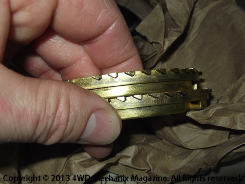
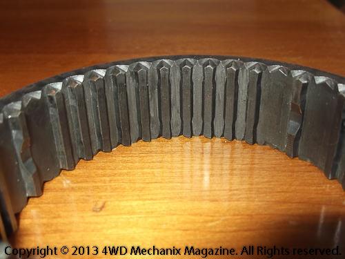
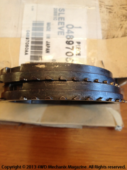
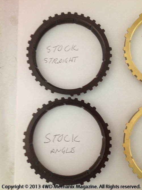
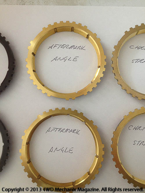
There has been a long thread of exchanges at Timmy960's topic on harsh shifting after rebuilding an AX15 transmission. The problem around 3rd/4th gear shift issues has a basis in the redesign of the synchronizer sleeve, bronze blocking rings and the third gear cog teeth for the sleeve engagement. Jason Logan and I had an exchange about this issue when he rebuilt his '99 TJ Wrangler unit. That exchange was just prior to the launch of the forums. For the benefit of all AX15 rebuilders, I am starting a new topic around this issue, beginning with the in-depth Q&A exchange that Jason Logan and I had...Since this exchange, Jason, Gary, Tim and I have been using the new forums to disseminate AX15 transmission rebuilding details...Here is the original exchange with Jason. I have highlighted important facts: Jason: Hello Moses! I have recently taken advantage of your detailed instruction on how to rebuild an AX15 manual transmission. I am currently working on an AX15 manual transmission from a 1999 jeep tj 4.0L that has never been rebuilt. I have a question regarding the stock 3rd and 4th synchro ring and the corresponding slider [sleeve]! The stock slider has an angle cut on one side and a straight cut on the other side. Also, the stock 3rd gear synchronizer is angle cut and the 4th synchronizer is straight cut. (I may have these backwards). Why is it that the dealer and aftermarket only show that both 3rd and 4th synchronizers are identical (either both are an angle cut or both are a straight cut). I ordered a 3rd and 4th synchronizer from Chrysler and they are identical (straight cut), and when I ordered a set from the aftermarket, the 3rd and 4th were also identical but with an angle cut! Should I use the Chrysler synchronizers (both straight cut), the aftermarket (both angle cut) or should I use one of each to replicate the stock setup as described above? I have put this rebuild on hold for weeks now trying to get some answers from many sources but nothing has been rock solid. I was hoping you could help me and give me some clarification on what is the best set up and why? Why does the slider [sleeve] have different cuts? Why do the replacement synchros have different cuts, different part numbers and configuration of teeth? Thanks for any information you can give me. Jason Logan These photos courtesy of Jason Logan ("JayDLogan"), forum member...Note the 3rd/4th gear sleeve and cog design for his 1999 TJ Wrangler AX15 transmission. Click on each photo to enlarge image. Moses: Jason, I would match synchronizers precisely to the originals and in their original locations. Measure the diameters of the rings, their angles and, most importantly, their fit against the synchronizer hubs in their correct positions. Make sure you face the synchronizer sleeve in the correct direction. Start with the original rings in correct relationship to the synchro hubs and sleeves. Note the overall “width” of the synchronizer assemblies, and then compare this with the aftermarket (new) synchros from both generic and Chrysler sources. The goal is to have synchro rings that will behave and fit just like the originals. Wear on the OEM rings is typically slight, perhaps a few thousandths, so you will know immediately if the parts are either wrong or in the wrong locations. AX15 synchro rings are not the same diameter, and the difference is slight, often confusing the assembly. My article provides details on the kind of “fit” and end plays you should achieve during assembly. Take your time, Jason, you’re already ahead of the game by questioning the parts to make sure of their fit and placement. The OEM layout and fit is your template. Match this and you will “restore” that AX15! Trust this helps…I’ll be at Moab through Thursday and out of communication. Let me know your findings in an Email. I will answer next Friday…Best of luck, I know you will do the right thing here… Moses Jason: Thank you very much for all of your information and help - my dilemma is - when I have ordered the synchro rings from Chrysler (they sent me 2 identical 'straight cut' synchro rings) and when i ordered from the aftermarket (they have sent me 2 identical 'angle cut' rings) but my original synchro rings have 'one of each' cut (one ring is a straight cut and the other ring is an angle cut). Although all synchro rings ordered are the same diameter, angles and fitment as my originals, I'm not sure if I should be using what Chrysler sent me (the 2 straight cut rings) or what the Aftermarket sent me (2 angle cut rings) - or should I be using one of each cut to match identically up to the original set up? I would have thought Chrysler would have sent me one of each (angle and straight cut synchro ring) based on the fact that my original rings are 'one of each' cut. And my second dilemma is - the number of teeth and location of the teeth on each ring ordered are not set up identically to my original configuration of teeth on my original rings - does that matter? I'm extremely grateful for your reply and value your expertise. Jason Logan Jason added these parts details: I found some other information, Moses! If you look at earlier years of the Jeep Wrangler 1997-1998 they have used part number 4897051AA (for both 3 & 4 synchro) or 4897052AA (for both 3&4) depending on the month the jeep was made. Part number 4897051AA is a synchro ring that has teeth that are angle cut and part number 4897052AA has teeth that are straight cut (shaped like a house). The jeep I am working on is a 1999 that calls for part number 4897052AA for both 3 and 4. It looks like at the factory, they have put part number 4897052AA for synchro 4 (near the input shaft) and 4897051AA for synchro 3 (near third gear). Very confusing! I also found, like I noted before in my second email, that the teeth of part number 4897052AA and 4897051AA are in a different configuration around the ring slightly than the originals as you can see in the pictures. I have purchased many 3 and 4 synchro rings but none of the teeth patterns match up! I had no problems matching up 1,2 and 5 synchros. I hope this helps you understand what I am up against! Thanks again! Jason Logan P.S I purchased part number 4897051AA today from Chrysler to clarify if it was angle cut and indeed it was! Moses: Hi, Jason, I’m just back from Moab, UT Jeep Safari…You sent great photos, this is all very interesting! Since the gear/ring in question is really 3rd gear, my belief is that Chrysler/Aisin discovered downshifting to 3rd problems and implemented a remedy. The angle cut would engage the shift sleeve differently, apparently allowing easier engagement on the downshift from 4th to 3rd. It would seem like either ring would work, as they each engage the sleeve troughs accurately (taking a straight-on view). The difference is that the angled ring would engage the sleeve with a different pressure and slight rotation of the ring. Just a guess, but this seems the only identifiable issue. Think about the third gear engagement: Shifting up, there is the lag in the shifter’s neutral gate and a “slower” engagement of 3rd gear. Shifting down, however, would be a direct, quick movement of the shift level and fork. Consequently, the sleeve would want to quickly rush over the brass ring teeth—without providing smooth or effective braking action at the gear hub. This would cause harsher gear engagement. Apparently, the slight angle makes the downshift to 3rd gear smoother, with better braking action and less risk of gear clash. Probably, either design would work if all drivers shifted up and down smoothly and without taxing the synchros. However, American drivers (and others with Jeep vehicles) want to affect a quick downshift to 3rd gear. The concern here, though, is to match the bronze rings with the updated synchronizer sleeve design. Does this make sense, considering the parts layout? The tooth spacing and offset on the rings has more to do with keeping the ring as close to square as it moves onto the gear hub. If nothing else, this is a testimonial to the precision design of Aisin transmissions, more like Euro types than U.S. gear products. The aim with a wedge ramp instead of arrow teeth is the shift “timing”, and that’s a precise consideration. This reflects the rest of the AX15 design quality and fitment. These are more complex units for a reason. I’m sure your build will be stellar, Jason! Let me know how this turns out. Regards, Moses Jason: Makes perfect sense Moses! Would it make sense to you to use the angle cut synchros for both sides of the slider even though the slider on one side is straight cut and the other is angle cut? I am still unsure if I should use both angle cut synchros, both straight cut synchros, or use one of each. The rebuild kit I purchased had two angle cut synchros, I am wondering if this is the upgrade? To me it is like rolling the dice on this decision! Thanks for all your input. Very much appreciated. Regards, Jason Photos courtesy of forum member Jason Logan...Note the OEM synchronizer design for this late version of the AX15—Mopar parts. Moses: I would follow the OEM approach if you’re sure the transmission is original, never before apart (which you believed from the start). The model year is late enough in the game for the synchro "solutions" to be in place…I would match the bronze rings and synchro sleeve carefully to the OEM layout. If this transmission shifted well for all of those miles, I would take this approach! As a final check, place the new synchro rings against the gear hubs to be sure the fit is aligned. You can put a light film of grease on the ring contact surface to read the fit. Wipe the grease away before assembly and coat the ring with a thin film of gear lube. Let me know how this all turns out, Jason… Best, Moses Jason: Thanks again Moses! I hope you had a successful trip to Moab, UT Jeep Safari. I have wanted to go for many years. Wish me luck on the AX15! Regards Jason Moses: Hi, Jason…Moab is breathtaking scenery, with contrast ranging from sandstone/slick rock to alpine peaks capped with snow this time of year, the Colorado River, arches and formations, all of it! I trust you’ll make it at some point, and if so, let me know. I do make the Moab Jeep Safari each year…Like Canada, we live at a “winter zone”, 4400 feet elevation near Reno. We look forward to winter’s end, and Moab Jeep Safari has become our annual end of winter/early spring gathering! You’re going to do a great job on this AX15! Follow the assembly steps faithfully, there are no shortcuts. When completed, you’ll have a smooth-shifting unit, as new, and that will be very gratifying! Let me know the outcome… I launched a message board today with a large number of forums at www.4WDmechanix.com/forums. It would be great to see your involvement if you have the time. Tech forums need detail-oriented members! It’s new, and I’d value your feedback about the forums you find interesting, the sign-up procedure, member validation and use. Best, Moses Note...Jason and I moved this conversation to the new forums at this point...When rebuilding an AX15 that has never been rebuilt before, lay out the parts as you take the unit apart, identify the synchronizer design for 3rd/4th gear, and match parts to the original design. There is a distinct difference between "earlier" AX15 and "late" AX15. The rebuild core in my magazine article and the A150 (Toyota version of the AX15) depicted at the Weber State University YouTube video (click for post topic threads containing the embedded video) are 1990-92 "early" AX15 design. Later model Jeep vehicles with the AX15 use a redesigned 3rd/4th synchronizer assembly...Rebuild accordingly, matching and using the right parts! Jason has added charts from an Aisin direct dealer that show the synchronizer applications for 1998-99 AX15 transmissions. Make sure you check your synchronizer rings and the synchro sleeve design for 3rd/4th gear. Install matching rings for your transmission. Be certain to install the synchro sleeve in the correct direction! ("House" or arrow shaped points match the 4th gear ring with house or arrow point teeth.) Here is an approximate application list with Aisin part numbers (not Jeep/Mopar): Click on image to enlarge...Thanks to Jason Logan for the chart!


-
Hi, Tim...There are two photos here, each looks like an original, worn brass ring. The one at the right shows the plates/keys cutting away at the brass. The damaged ring was rotating considerably. What was the condition of the plates/keys at the 3rd/4th gear synchronizer? The ring at the right has straight "arrow" shaped teeth; the ring at left has offset/angled teeth. The ring at the right should be 4th gear for your later, 1999 AX15 unit. Correct? Since I cannot see the new ring (please upload the third photo), I'm not able to determine whether the new bronze ring has straight arrow shaped teeth or offset teeth. As Gary suggests, on these later AX15 units, 3rd gear has a unique cog tooth arrangement (angled ramp shape, not arrow shaped). This fits with a unique brass ring design (which has offset crowns on the teeth). The generic aftermarket rebuild kits apparently do not have offset teeth at the 3rd gear bronze synchro ring. Aftermarket kits often pattern a specific year(s) design. The earlier AX15 has arrow-shaped 3rd gear cog teeth and arrow-shaped teeth on the bronze ring—not the offset or ramping design. Both my magazine rebuild article and the Weber State University video demonstrate an earlier version of the AX15: 1990-92 vintage. This 3rd gear synchro issue came up in JayDLogan's AX15 build, which is also a later Wrangler application. He and GaryT discovered that Chrysler/Mopar offers a unique part number for the 3rd gear bronze synchro ring plus a unique 3rd speed gear for these later AX15 applications. (I can furnish Mopar part numbers for the '99 3rd speed gear and the 3rd gear bronze synchro ring if you need these numbers, Tim.) In this topic's threads, GaryT uploaded photos of the later 3rd gear design found in his '99 TJ Wrangler AX15 rebuild. GaryT, Jason (JayD) Logan and I have each raised questions about the bronze ring for a later AX15 3rd speed gear. The angled/ramping gear cog teeth may require the offset-point bronze ring teeth like in your photo at left (presumed to be the 3rd gear bronze ring?). Please clarify which ring fit where in your AX15, Tim. 4th gear appears to be the badly damaged ring at right with straight-arrow shaped teeth. Aftermarket suppliers may need to offer an "early" and "late" rebuild kit—or specific "early" and "later" 3rd gear bronze synchro rings to accommodate the 3rd gear cog/teeth design change. For some solid insight here, I started a brand new thread (click here) on the 3rd/4th synchronizer design change. Jason Logan (our fellow forum member JayDLogan) and I began an exchange just before these forums launched...I revisited that Q&A and added our exchange as a new thread. At the new thread, you will find some insightful photos by Jason plus a valuable clue: the later AX15 transmission uses a different 3rd/4th gear synchronizer shift sleeve. If installed backward, especially with the wrong synchronizer ring match, this sleeve would raise all kinds of trouble with shifts between gears! Take time to read and review the photos at the new thread, Tim. Our discussion should resonate... Moses
-
Postscript on GARYT's comment...If the 3rd gear has one kind of ramp design, and the synchronizer ring has another, this could cause an issue as Gary suggests...Tim, do your remember the design of your AX15's 3rd gear cog teeth: an angled ramp or arrow-shaped? Do you recall the design of the 3rd gear bronze ring teeth: either angled teeth or arrow-shaped teeth? Moses
-
Tim, we're each being thoughtful about the AX15. The aim is to make rebuilds perform as new—perhaps better. Gary and I have batted ideas back and forth about improvements to the 1st/2nd synchro and sleeve assembly. 3rd/4th has presented less of an issue, though there is the puzzling Aisin changeover to the angled 3rd gear cog ramps and bronze synchro ring tooth shape...This indicates something inherently challenging about the 3rd gear shift. You are spot on with your detent analysis if each gear position produces a shift lever feel of "holding" when the lever is in the selected gear position. The 15 mph with a double clutch downshift indicates that the problem is synchronizer related. Essentially, at that road speed and with a double clutch effort, you can synchronize the input and output shaft speeds to the speed of 3rd gear. As a segue, I once owned a '51 F3 Ford truck with a "spur gear" four-speed transmission (totally non-synchromesh on any gear with rugged straight-cut gear teeth). I taught myself to use the clutch pedal only at complete vehicle stops. Once moving at all, I could shift up or down through every forward speed without depressing the clutch pedal—and without clashing gears. While this may sound unique, it really wasn't. Older truck and car drivers (well into the 1930s) downshifted straight-cut, non-synchromesh transmissions by either braking the vehicle or accelerating enough in neutral to sync the engine and output shaft speeds for a desired gear's ratio. At the correct vehicle speed, engine speed and output shaft speed, the clutch pedal was dipped, shifter moved to neutral, then the clutch pedal released momentarily in neutral. Only if necessary, the throttle was blipped to change the engine speed slightly to match the output shaft speed for the next gear down. The clutch pedal was dipped again (the "double-clutch" effect), and the driver moved the shifter into the downshift gear before smoothly releasing the clutch pedal. For a non-synchromesh gear, the trick is to have engine speed match the desired gear speed and the output shaft speed. In good time, you can learn to shift flawlessly and "know" when to affect a shift to each gear—braking and accelerating as necessary to "synchronize" shaft and gear speeds. Along came synchronizers—for Ford light truck buyers, the solution came with the 1952 introduction of the T98 four-speed transmission. I'm forever grateful for that '51 Ford F3 "learning experience" and have instructed four-wheelers on how to get home from the backcountry with "clutch-less" shifting—like when the clutch mechanical or hydraulic linkage fails...In your case, Tim, you discovered the "sweet spot" for third gear downshifting when the synchronizer proved ineffective. Your problem is definitely related to the 3rd/4th synchronizer assembly. Unless you have the wrong lubricant in the unit (please share details so we can determine whether that's a factor), the problem will be the hub springs, keys/plates or a thrust washer out of position or missing. In the case of the hub springs, they must be staged properly. Click here to the magazine page on the AX15 rebuild. Read Illus. AX15-104 to AX15-113 carefully. I describe the alignment of the plates (keys) and springs in detail for both the 1st/2nd and 3rd/4th synchronizers. Throughout the assembly discussion, I outline the direction that the gears and synchronizer hubs face—plus the location of thrusts and critical thrust endplay measurements. In the Weber State University video, the instructor talks about bronze ring gap measurements as a determinant for ring wear. There is also the issue of placing the correct ring at the correct position. The brass rings in an AX15 can look very similar; however, when placed in the wrong position, the ring will mate with the gear hub incorrectly and not create the needed braking action for "synchronizing" the gear's speed with the hub/shaft. I am confident that you will find a distinct problem with either the 3rd/4th synchromesh assembly or the 3rd gear/brass ring fit-up. When you do, please share with us, as your comments could be beneficial to others. Do not hesitate to post questions. The AX15 is not a simple transmission to rebuild. When I decided to share rebuild steps, I knew this unit was complex and took a "textbook" or "blueprint" rebuild strategy. Anyone tackling an AX15 rebuild will be challenged. Everything has to fit correctly and precisely, clearances are critical, and parts alignment is only correct if every single step falls into place properly... I have been rebuilding manual and automatic transmissions professionally since 1969, methodical and painstaking when rebuilding transmissions with close tolerances. The AX15 is much more a European kind of gearbox than a historical Jeep unit. Tolerances are closer, the cases will only fit with all parts aligned—and that's just the beginning. The AX15 has a steep learning curve... Moses
-
Agreed, Gary...See the YouTube video: In this video (above), an instructor at Weber State University shares the gear functions of a manual transmission and synchronizers. For the benefit of AX15 builders, the demonstration unit just happens to be a Toyota version (A150) of the AX15 transmission...As Gary notes, and you all will see within this instructor's 24-minute video, the synchronizer sleeve for 1st/2nd gear does not engage the 1st and 2nd gear cogs as deeply as the 3rd/4th gear synchronizer sleeve engages the 3rd/4th gear cogs during shifts. Although the view is not as clear, the 5th gear sleeve engagement also appears shorter than 3rd or 4th gear. Note: To save time, view the shift sequence and parts alignments from approximately 7:30 to 23:00 minutes. The entire video is helpful if you want to understand the functions of a synchromesh transmission and how gear speed ratios work...As an automotive technology instructor, I would like to thank Weber State University and the instructor for making this video available as a "public" YouTube download. The unit in this video is a 1992 version. The unit I step-by-step build at the magazine article is also from the 1990-91 era. Note the shape of gear cog teeth from that period. Cog teeth are all arrow shaped, none are the angle shape found on the later 3rd gear in Gary's photos from a 1999 AX15. Our concern here is whether this short sleeve engagement is inadequate for 1st or 2nd gears (possibly 5th, too). Gary noted the short sleeve throw while rebuilding a 1999 TJ Wrangler AX15 transmission: The 1st/2nd gear shift sleeve does not engage the 1st and 2nd gear cogs to the same degree as the 3rd and 4th gear sleeve engages the 3rd and 4th speed gears. Has anyone else made this observation during an AX15 rebuild? Both Gary and I question this short throw of the 1st/2nd gear synchronizer sleeve when engaging either 1st or 2nd gear. Does this lead to trouble? In particular, can this cause the transmission to jump out of 1st, 2nd or even 5th gear? Moses
-
Gary, welcome to the forums! Thanks for providing AX15 parts photos...Tim talks about a 3rd gear downshift problem. Your photos suggest that Aisin may have addressed a downshift to 3rd gear problem. The angle cut you describe and share in your photos would engage the shift sleeve differently. This would allow easier engagement on the downshift from 4th to 3rd. From a practical standpoint, either ring would work, as they each engage the sleeve troughs accurately (taking a straight-on view). The difference is that the angled ring teeth would engage the sleeve with a different pressure and slight rotation of the ring. This is the readily identifiable concern... Think about the third gear engagement: Shifting up, there is the lag in the shifter’s neutral gate and a “slower” engagement of 3rd gear. Shifting down, however, would be a direct, quick movement of the shift level and fork. Consequently, the sleeve would want to quickly rush over the brass ring teeth—without providing smooth or effective braking action at the gear hub. This would cause harsher gear engagement. Apparently, the slight angle makes the downshift to 3rd gear smoother, with better braking action and less risk of gear clash. Probably, either would work if all drivers shifted up and down smoothly—without taxing the synchronizers. However, American drivers (and other Jeep 4x4 owners) want to affect a quick downshift to 3rd gear. Another consideration is driving in low range of the transfer case—the 3rd gear downshift problem would be even more exaggerated! If nothing else, this is a testimonial to the detailed design of Aisin transmissions, more like European types than traditional U.S. gear products. The aim with a wedge ramp instead of arrow-shaped teeth would be the shift “timing” and precise angle of engagement. This reflects the AX15's overall design quality and close-tolerance fitment. Aisin and European transmissions are more complex units for a reason... Does this make sense, considering the parts layout? As for the tooth spacing and tooth offset on the brass rings, this would keep the synchronizer blocking ring square as it moves onto the gear hub. Great to have you at the forums, Gary! Looking forward to your sharing...Moses
-
4.0L Block Holes
Moses Ludel replied to WMCCALL's topic in Jeep® XJ Cherokee, MJ Comanche Pickup and Grand Cherokee
Wayman, from what I saw, there is really no need for J-B Weld. If you just smooth out the casting "flash" and leave a solid casting, you'll be in good shape. Do not remove structural material. The oil transfer hole at the timing cover area of the block should simply require shaping the rough flashing edges to reduce risk of sloughing. I saw no point in adding J-B Weld. What's your thought there? To provide some peace of mind, I found this definition of casting "flash" to help you better understand the issue: http://www.abymc.com/tmoranwms/Casting_Defects.html Trust this is helpful...On the issue between the two lifter bores, send me a close-up photo that details your concern there. Moses -
water in transmission
Moses Ludel replied to rvharry's topic in Jeep® YJ Wrangler, TJ Wrangler and LJ Wrangler
Hi, Harry...Happy Mother's Day to the ladies in your family! Sounds like you got a partial drain of the system. Actually, an automatic transmission can get hot enough for the water to separate and steam out the vent if you're very lucky, in which case you still need to top off fluid. As a footnote, always check fluid with the parking brake set, wheels choked and engine idling with fluid warm in NEUTRAL. RWD Chrysler 999 and 30RH/32RH units will not show correct fluid level in Park. Are you still experiencing the 'stuck in first gear'? Has that resolved, or are you working your way through my comments and checklist? Firing up the barbecue here, will watch for your reply...Moses -
4.0L Block Holes
Moses Ludel replied to WMCCALL's topic in Jeep® XJ Cherokee, MJ Comanche Pickup and Grand Cherokee
Okay, Wayman, this looks a lot better! I pored over the Hewes Performance videos to find the best image of your "hole". At http://www.4wdmechanix.com/HD-Video-Jeep-4.6L-Inline-Six-Pistons,-Rods-and-Bearings.html, check around 4:04 minutes, with the HD mode in full-screen view...You'll see a "hole". This is a casting design, likely to drain pooled oil from the lifter area and provide more timing chain lubrication in the process. Sounds like you're doing a detailed rebuild and observed the rough casting edges at the hole. Unfortunately, casting flash is common on cast iron, mass produced engine blocks. I always go over the block and assess what poses a threat of sloughing off fragments—the risk of a piece of casting migrating into the crankcase or between moving parts. The rationale "well it stayed put this long" doesn't work for me, and apparently, you're discriminating, too. If in doubt, take a die-grinder with carbide burr tool and smooth out the rough edges to the point that the casting looks stable, nothing excessive, just enough to remove the threat of sloughing. Always remove debris thoroughly, including any fine iron powder from the grinding process. This is abrasive stuff! Make sense? Does this confirm what you're looking at? If so, don't attempt the use of J-B Weld—if the patch doesn't set well or is affected by oil over time, J-B Weld or similar materials could slough and end up in the oil pan. The threat here is plugging up the oil pump pickup screen, although it would take a lot of J-B Weld fragments to create a significant problem. As a footnote, my remarks are not intended to detract from the value of J-B Weld...I can think of many occasions where the right J-B Weld product has been a tremendous asset: as an emergency trail aid or inexpensive way to save an expensive, damaged part—like a non-stressed motorcycle side cover with a chip or crack. Trust this helps, Wayman... Moses -
You're welcome, Jason! Let me know how your "blueprint" rebuild turns out, it's almost summer now, and you must be itching to go 'wheeling! Moses
-
Comp Cams Choices?
Moses Ludel replied to WMCCALL's topic in Jeep® XJ Cherokee, MJ Comanche Pickup and Grand Cherokee
Wayman, this question comes up consistently, and of course, you should read footnotes from the manufacturer's listings. The camshaft I recommend with the 4.6L stroker build, and with the Mopar EFI conversions on the 4.2L, is the CompCams 252 grind—not the 232. Tony Hewes and I both run this camshaft in fuel injected inline six-cylinder engines without issue. The grind has been around for a long time, I first tried it on 383 Chevy SB V-8 stroker motors built for off-road use and trailer pulling in the late 1980s/early '90s timeframe. It was phenomenal for low-end torque, a lower rpm ceiling (4,200-4,600 rpm, will run out around 5,000 rpm) with peak torque by 2000-2400 rpm, depending upon engine application. Manifold vacuum at lower speeds is excellent. All of that said, my first use in an inline six was a Ford 300 with MPI. It ran flawlessly, again with a quick torque rise and great bottom end. Move to the 4.0L and 4.2L or 4.6L Jeep inline six, again a success story. The 4.6L in the '98 XJ Cherokee that I talk about in the vlog discussion was built by Hewes Performance with the 252 grind, as was the 4.6L in the CJ-8 Scrambler walk-around video. This camshaft delivers! I use it...We've run the cam with stock injectors and with Ford 24 pound injectors in 4.6L Jeep buildups. Perhaps CompCams wants to avoid emissions controversy here, although there's no reason to suspect higher tailpipe emission readings...We've seen no check lights, either, even with the 24 pound injectors. We're holding compression to 8.7:1. Moses -
4.0L Block Holes
Moses Ludel replied to WMCCALL's topic in Jeep® XJ Cherokee, MJ Comanche Pickup and Grand Cherokee
Wayman, I took the initiative to look at your pics in the photo bucket. The chipped section between the lifter bores is not a great issue, though you should smooth out the rough edges that might slough off iron in service. The other break concerns me. Is this a punched out block section at the timing cover area? What's on the back side of the break/hole? Is this the thin casting where the block timing cover section extends out from the block? The real concern is loss of oil or an opening into a cooling jacket. From what you're suggesting, it sounds like this hole/break opens away from the block's cooling jackets or ports. That would be critical. You still need to contain oil in the engine, as the timing cover area has a high wash of slinging oil. Let me know what's on the other side of the break. If there's any way to fix this hole in the casting, your main concern is to grind off any material that could slough off into the crankcase or find its way between moving parts. I'm not a huge fan of J-B Weld, however, it will work in areas that do not have pressure or excessive heat. J-B Weld is around 3,000 psi tensile and works to around 300 degrees F, depending upon the type of J-B and cure time. This is not a lot to get excited about when you consider an iron block is typically 40-50,000 psi tensile and can get good and hot in service. If you can, take a picture of the hole's backside, so I can get a better perspective. I TIG weld cast iron, using Weld Mold 700 and 750 filler with great results. See this link for an example of my TIG repair of cast iron: http://www.4wdmechanix.com/TIG-Welding-Technique.html. Careful bronze or silver brazing can also work in an unstressed area cast repair, as long as there's no concern about warping or you can square the slightly distorted surface with either a milling machine or careful hand mill filing. Such repairs depend upon the size of this hole/break and the equipment available. Moses -
Hi, Tim...The shift balls, springs or plug theory could be happening, parts out of order; however, before you tear a freshly built unit down, try feeling the detents for each gear. If the third gear and fourth gear detents make a distinct "click" into place, the detents might be okay... This could be a binding or cocked shift fork or sleeve. Did you replace brass blocking rings, bearings, and so forth? Third and fourth gears have a much better engagement on the AX15 than 1st/2nd does. The shift sleeve for 3rd/4th moves thoroughly over the gear cogs, which the 1st/2nd sleeve does not in some AX15 applications. Is there gear clash? That would be more symptomatic of plugs out of place or missing, as the shifter would be trying to catch two gears at one time. 3rd/4th is on the same rail and should not cause a sticking problem unless there is cocking or binding, something like the synchro hub springs and keys not indexing properly. This would allow a key to raise out of its notch in the hub, which is a real possibility with what you're experiencing. Properly positioning the synchro hub springs and keys is essential. Let me know more details, we'll kick this around...Moses
-
AX-15 Torque Capacity?
Moses Ludel replied to WMCCALL's topic in Jeep® YJ Wrangler, TJ Wrangler and LJ Wrangler
Wayman…The AX15 in “new condition” can handle 300 hp and 300 ft-lbs torque. They do hold up when in top condition and not subject to abuse. This unit is on par with an NV3550. Neither is exemplary, both will handle horsepower and torque in the range you describe. I would say they are less robust than a “World Class T-5” from the 302 H.O. days, but not by a lot…300 ft-lbs is not extreme. Advance Adapters does a brisk business on V-8 adapters for the Jeep/AX15, if that’s a good indicator. There are many conversions out there. In my later builds, which lean toward “truck” type gearing and ratios, I’ve opted for the NV4500, which eliminates any guesswork. I am not averse to a SBC or Ford 302. For Ford, I do prefer a 351W for crankshaft stamina, and both the 302 and 351 have the distributor conveniently at the front of the engine. There are emission requirements for swaps if that’s an issue in your area. The Jeep stroker 4.6L works well, and the only “modification” beyond that is the use of 302 Ford V-8 24-pound injectors. Everything else should work…To produce 300 horsepower, however, requires a bigger cam and compression, which may make emission tailpipe readings go sideways. I use the milder CompCams 252 grind with 8.7:1 compression, and tailpipe readings fall within norms. The inline six produces an altogether different kind of power. You’d like the 4.6L stroker better for bottom end torque and a quick torque rise, useful for off-road driving and for fuel efficiency at cruise…Apples and oranges, if you want brute horsepower, there’s no substitute for cubic inches: a SBC, G.M. LS or Ford small block V-8. Moses -
Jason, these bearings are very durable. If the original bearing's radial/axial fit does not allow more movement than the new set, the original will likely work fine...It's always about tolerances and any signs of heat damage or sloughing of metal. I'd be okay with the reuse of the original caged needle bearing if within tolerances with no sign of heat damage. The case hardened shafts and gears, plus bearing steel, are all hard stuff!...Moses
-
1997 XJ Wiring Issues?
Moses Ludel replied to WMCCALL's topic in Jeep® XJ Cherokee, MJ Comanche Pickup and Grand Cherokee
These can be specific problems or just more common issues. Our '99 XJ Cherokee has a TSB on the instrument cluster wire sets, and I'll be doing a factory repair splice of new connectors to eliminate the tach/speedo/check light bug that occurs when the instrument panel parks in the sunlight. (Never acts up beyond this but when it does, this is annoying although intermittent.) If you have a specific issue, let me know, I'll check the TSBs and do a bit of research on your behalf.—Moses -
water in transmission
Moses Ludel replied to rvharry's topic in Jeep® YJ Wrangler, TJ Wrangler and LJ Wrangler
Hi, Harry...Welcome to the YJ/TJ Wrangler forum, thanks for joining! There is a spirited, technically-inclined community building here... Wow, I got the visual on the Wrangler parked in a mud puddle with a Torqueflite transmission. Barring mechanical troubles like a throttle valve cable sticking or dislodged, the other possibilities for your transmission sticking in first gear are either the governor valve stuck closed or a valve body problem like the 1-2 shift valve stuck or the governor plug stuck. When you mention the fluid change, I'm assuming that the filter got changed as well. The system probably required a complete flush at a shop equipped to exchange all of the fluid. Otherwise, water in the unit simply pumped into the converter, and if only the pan fluid got changed, there is still that water within the converter—which recirculated through the entire transmission. I'm an optimist about the fluid contamination as long as the filter was working and sealing properly. This should have prevented any mud debris from reaching into the valve body. Agreed, the vent valve is another story, and I do recommend extending the vent to the top of the firewall in the engine bay if possible. Oil-resistant hose, quality EFI hose clamps and some fittings can implement this change...Where is the factory vent valve located, Harry? Is it accessible? Another consideration is the speedometer drive, which also interfaces with the PCM. This can fault, especially after submersion in muddy water! Clean and check connections. Make sure there is no MIL light on ("Engine Check"), suggesting a problem with the speedometer signal that could effect the shifts. If there is actually contamination within the valve body, that's time to consider the Sonnax upgrades during a valve body rebuild. (Follow the link to my how-to on upgrading the valve body.) I'm not sure whether you found mud inside the transmission, and again, the governor is likely okay if the sump filter worked properly. As for any RWD Chrysler transmission of this type, there is always the anti-drainback valve issue. If contaminants reached that valve, you will have issues with both internal pressure and cooling of the transmission. The Sonnax upgrade is the only way to eliminate this pesky valve—those who otherwise remove it without consideration for the anti-drainback needs of the converter and transmission will toast the front pump bushing eventually. Trust this helps, I'm here for more dialoguing and clarification...Go through my comments carefully...Share what you know, I'm pleased to respond...Others can weigh in, too! Moses P.S.: We do love our grandkids, right? Our youngest is 14 months old, they range to college age…The baby has begun to walk…This will keep us in shape! -
Agreed on the oil, Pete, you're in bearing survival mode from what you describe, although the rattle should also be at low speed throttle tip-in. Separate detonation/ping from lower end rattle. The cranking compression actually sounded high, possibly carbon buildup on the pistons and combustion chambers. I like to use a cylinder leakdown test to get a real sense for wear. Cranking compression can be deceiving with cylinder taper; a leakdown is performed at TDC for each piston, the point with maximum cylinder taper/wear...Stick with the 20W-50, for sure, as long as you are not in a cold weather zone with starting issues. Your manual choke test on the BBD was very telling. The carburetor is either jetted lean or not flowing enough fuel for the incoming air. (There is still the possibility of an air leak, which would create a lean factor. Check for manifold and carburetor base leaks as I suggested, it will only take a few minutes.) Your attempt to change running condition with the choke is very revealing and helpful. Most engines do not have a manual choke provision, so that test would be impossible on the road unless you close the automatic choke down then road test. There is a definite lean condition, eliminate possible causes as I outlined in earlier replies... The five-pin Chrysler module is very slick. You are simply converting your Motorcraft distributor to a real time ignition, eliminating the interference of the ECU and Ford-type Motorcraft ignition module. The module I describe is early Chrysler electronic distributor and should be available through NAPA/Echlin still. I actually learned this trick in the late '80s from Jacobs Electronics. They discovered that the Motorcraft distributor can readily work with the five-pin Chrysler module and the correct wiring hook-up. You then have true centrifugal and vacuum advance from your stock 4.2L Motorcraft distributor...Vacuum without interference requires following my earlier suggestion about a simple routing of vacuum from the carburetor ported source, through the CTO, to the distributor vacuum canister. (If you don't care about vacuum advance elimination with a cold engine, you can route a hose directly from the carburetor ported source to the distributor vacuum canister.) The Motorcraft distributor should work well with its stock centrifugal advance and vacuum spark timing—without interference from the ECU. I've scanned and attached the PDF of a 1977 Dodge 225 inline six BBD carburetor bench adjustment list. Since your carburetor has a manual choke, most information is not relevant. Pay attention to the float level and pump setting. If your carburetor is truly '77 in origins, it will not have a bowl vent that is adjustable...There's little left beyond fast idle settings...Check the float height and pump setting. Make sure the needle is not sticking in the seat. The wild card, Pete, is whether your Brand-X "rebuilt" carburetor has the right body parts and jetting for that application. Jet sizing is not included in service information from that emissions era...I trust this limited information helps. Based upon the manual choke test discovery, you may be bucking a low fuel supply or a low float setting in the carburetor—or air leaks that would lean out the mixture...Moses BBD Carburetor Settings.pdf
-
BG, I am confident that a sharp Toyota parts counterperson will have access to this information and turn up the snap ring in the right size... Let us all know, the AX15 parts chase may be easier with Toyota in the loop...Also curious what Toyota charges for the snap ring. The multi-year debacle at Chrysler sent parts sourcing and inventory into the ozone—and pricing apparently hasn't come back to Earth yet! I'm optimistic, Chrysler Group returned a $166M net profit for the first quarter of this year. With financial stability and debt elimination, Mopar parts inventories and pricing should improve!—Moses