forman
-
Posts
115 -
Joined
-
Last visited
Content Type
Profiles
Forums
Blogs
Store
Articles
Gallery
Everything posted by forman
-
Rebuilding a Jeep CJ-7 Dana 300 Transfer Case
forman replied to forman's topic in 1972-86 AMC/Jeep® CJ and Jeepster Models
I contacted John Compton today, a very nice fellow, and we discussed my situation and he is checking availability of my parts. You should give him a call Moses he was asking about you. -
Kawasaki KLR Motorcycle Engine Teardown and Inspection
forman replied to forman's topic in Dirt & Dual-Sport Motorcycles
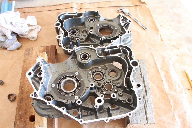
Its been awhile since I could focus my attention to this engine. I've been cleaning and inspecting not only the parts but my previous work. So far I have found that all parts were assembled correctly. I mentioned earlier that this engine was so completely wrecked and there are abrasion marks inside the case from the wreck previous to my last rebuild that prevent me from being able to pinpoint the source of fine aluminum flecks that I found in my oil. The particles could have also been from an incomplete cleaning that I gave the engine parts, I think especially the clutch parts. I don't think I'm going to be able to find the source if it exists. I was able to measure with a dial caliper across the piston skirt as per the KLR manual and determine that the piston has exceeded its service limit and must be replaced. This also means that I will need to bore the cylinder if I choose to use this engine. I placed the parts in the crankcase and took a few photos... The two case halves The transmission input shaft (left) and output shaft The input and output shafts shift forks and shift drum in place The right crankcase half with all components in place


-
Rebuilding a Jeep CJ-7 Dana 300 Transfer Case
forman replied to forman's topic in 1972-86 AMC/Jeep® CJ and Jeepster Models
I’m considering an upgrade kit rather than used parts. Do you have one that you could recommend? I looked at the Lomax gear from JB Conversions but was unsure if I needed to buy additional shafts along with the gears. Confused about what to do here and don't want to make a costly mistake. -
Rebuilding a Jeep CJ-7 Dana 300 Transfer Case
forman replied to forman's topic in 1972-86 AMC/Jeep® CJ and Jeepster Models
I use a Canon 60 D camera and I believe that I was using a 55 - 135 EF-S kit lens. I was also very close to the little buck fawn I was photographing. I have discovered that the intermediate gear is no longer being produced so my options have been narrowed... I can replace all of my small parts with a Dana 300 master kit including intermediate shaft and hope for the best, or upgrade. I really don't need an upgraded lomax type of transfer case but I was wondering if you knew of any other moderately priced kits? To be honest the stock transfer case is all that I need for the type of 4 wheeling we do here on this ranch. -
Rebuilding a Jeep CJ-7 Dana 300 Transfer Case
forman replied to forman's topic in 1972-86 AMC/Jeep® CJ and Jeepster Models
I should answer your question about reasonable restoration. Yes that is the right answer for this Jeep. The engine was replaced about 4500 miles ago with a rebuilt 4.2 I6. Soon we should talk about the under the hood problems and options. Deep down inside I would love to rebuild and upgrade as much as I was capable of but that is just not an option with this Jeep, Perhaps when I retire I can buy it as surplus and go from there?? -
Rebuilding a Jeep CJ-7 Dana 300 Transfer Case
forman replied to forman's topic in 1972-86 AMC/Jeep® CJ and Jeepster Models
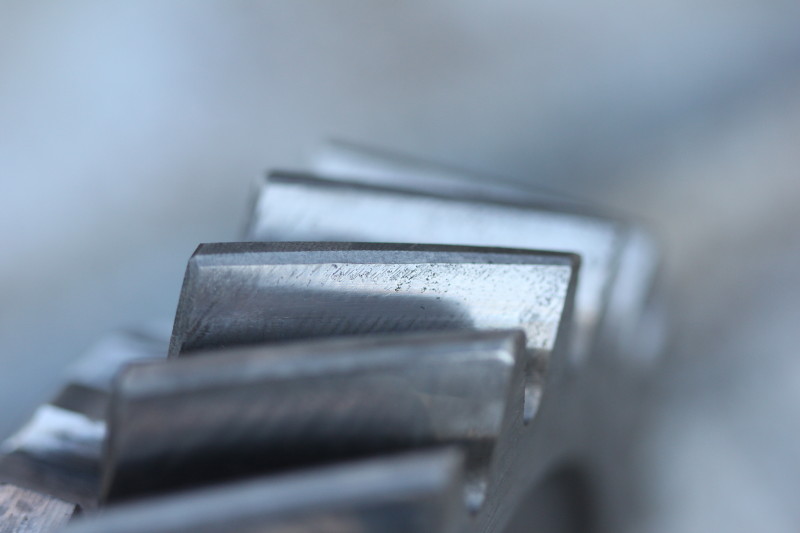
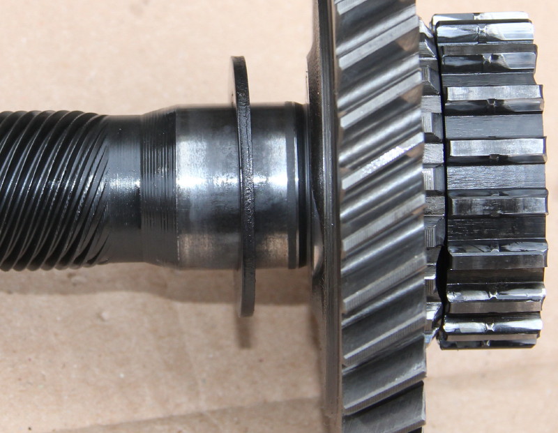
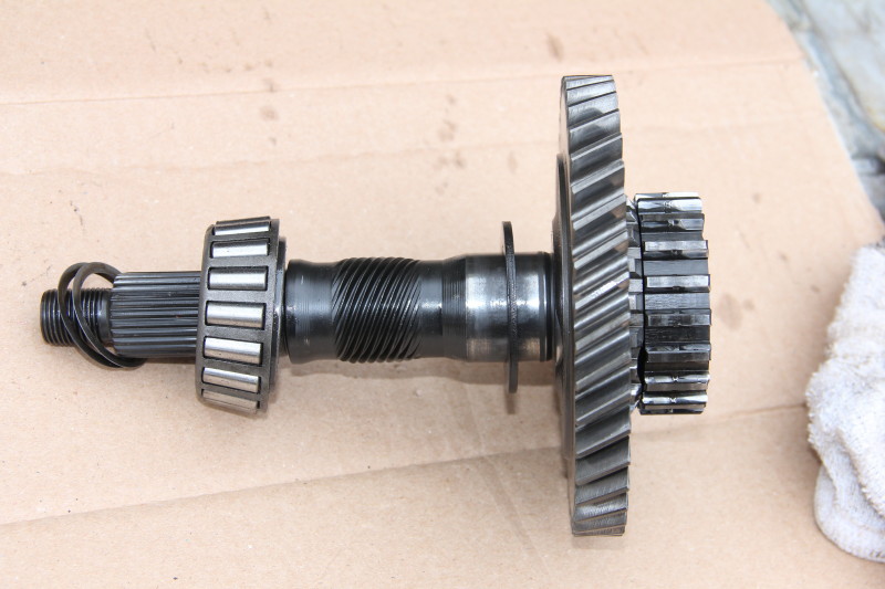
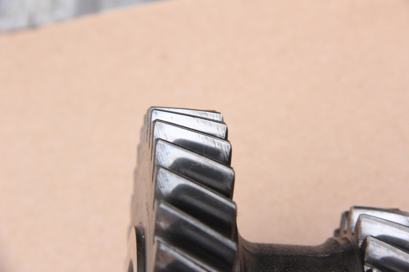
Thanks Moses here is a picture of what I usually take photos of. These photos are of gear teeth associated with the front output shpaft This photo is of the large gear of the transmission input assembly This Jeep will probably never see asphalt or highway speeds again, in fact that has been true for the past 15 years. 90% of the time it is in 2H, 4H when it is muddy (almost never) and 4L when climbing usually for about 3 minutes at a time. Never over 30 mph. I love riding through the pasture with the top down and windshield lowered, it is quiet and comfortable... conversation with others is easy. I have to say that the lurching is annoying, I'm ready for it to be gone. The rear axle is probably next!


-
Rebuilding a Jeep CJ-7 Dana 300 Transfer Case
forman replied to forman's topic in 1972-86 AMC/Jeep® CJ and Jeepster Models
I think I know the kind of photos I need to take for you to be able to see what kind of shape the gears are in. Theses few are marginally good enough, I'll give it a little more effort and post some more later. I am not sure the problems with my drive line are limited to the transfer case, I'm pretty sure the rear end has some issues also. I don't wish to make troubleshooting more difficult. I'm just stating the facts. My budget for repairing the transfer case would be enough to restore with factory parts, if those are difficult to find or super expensive I might be able to buy aftermarket parts toward an upgraded condition.


-
Rebuilding a Jeep CJ-7 Dana 300 Transfer Case
forman replied to forman's topic in 1972-86 AMC/Jeep® CJ and Jeepster Models
I had the best intentions of getting a great video of a sloppy gear on its shaft. What I got was just an ok video where the gear to shaft play is difficult to see. I used grease to help the needle bearings and spacers stick together and make it easier to assemble. It was cool today and the grease felt thick and sticky so I think the grease would make the tolerances seem tighter. Here is the video and a couple of close ups of the intermediate large and small diameter gears. I had .013" clearance between the gear and the case wall, The shaft is worn and the wear is easily felt while sliding a finger along the shaft.

-
Rebuilding a Jeep CJ-7 Dana 300 Transfer Case
forman replied to forman's topic in 1972-86 AMC/Jeep® CJ and Jeepster Models
The oil was thin smelly and leaking out. I expected to find worn parts. I found no gaskets while tearing down the transfer case, so I"m assuming it has been rebuilt before. I apologize for taking so long and stretching this out but I am just busy putting out fires at work and home. As for the other gears I have some questions that can be best answered by viewing photos so I'll get busy with that. Thanks Moses I will assemble the gears and try to get a video of the clearances and play. -
Rebuilding a Jeep CJ-7 Dana 300 Transfer Case
forman replied to forman's topic in 1972-86 AMC/Jeep® CJ and Jeepster Models
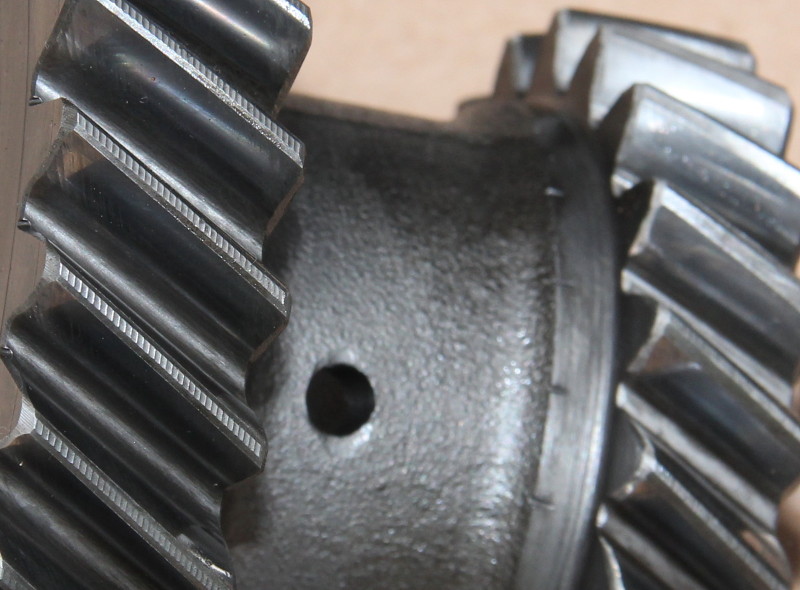
I found a little time to clean some of the parts today. I thought I would post some photos for reference and to ask for assistance in understanding the condition of certain worn areas. The intermediate gear minus the needle bearings A close up A close up of the shaft worn area the gear and interior close up


-
Kawasaki KLR Motorcycle Engine Teardown and Inspection
forman replied to forman's topic in Dirt & Dual-Sport Motorcycles
Moses in this photo the pitting or erosion is very evident but while looking with the unaided eye this looks like a stain on the cylinder wall. I'm thinking that the microscopic pitting maybe normal to some extent. I know that LA Sleeve claims to make a better cylinder out of better material and also several KLR owners complain of out of round cylinders that wear abnormally and loose compression. Just thinking out loud... I've got the original cylinder the grenade went off in I'll take a closer look at it tomorrow.
-
Kawasaki KLR Motorcycle Engine Teardown and Inspection
forman replied to forman's topic in Dirt & Dual-Sport Motorcycles
A shot of the interior right side crankcase no small pieces of aluminum. The piston I was trying to photo the skirt bottom to show wear if present The next shots show some wear on the skirt but minimal I think The ring gap was out of spec and nearing the service limit on both rings. I think this is a cast iron cylinder a stock KLR cylinder


-
Kawasaki KLR Motorcycle Engine Teardown and Inspection
forman replied to forman's topic in Dirt & Dual-Sport Motorcycles
The cylinder wall at first appearance was very shiny with a glazed almost mirror finish. My photos show that cross hatch markings are visible as well as several other inconsistencies in the metal like small pitting hardly visible to the naked eye, also some minute travel markings left by the rings as they rode up and down the cylinder wall. The last photo is a really cool looking close up


-
Kawasaki KLR Motorcycle Engine Teardown and Inspection
forman replied to forman's topic in Dirt & Dual-Sport Motorcycles
I will get some photos up today. The head was professionally rebuilt I knew that replacing one valve face, the two exhaust rod guides, and two bent valves would surpass my skills. Valve seals were replaced with Viton seals. I do not have the tools to measure the piston or inside the cylinder... I will work on that though, any recommendations? The inside of the cylinder where crosshatching should be is like glass, The rings were just within specification. I do not know the history of this piston and cylinder, they were from a donor engine that I bought off of craigslist that was supposed to have only 4000 miles. I realize that some of my choices while rebuilding this engine were inconsistent for instance I replaced all bearings and seals instead of just the obviously bad ones. While I bought a donor engine and used the cylinder, crank and piston without refurbishing the used parts, my skills were lacking and I chose to slap those parts in and move on. That is why I am in the situation I am in now. I am confident that with your help I'll get this engine running like it is supposed to. Then again that is why I bought the $100 dollar engine with the stripped oil plug as a possible replacement. -
Kawasaki KLR Motorcycle Engine Teardown and Inspection
forman replied to forman's topic in Dirt & Dual-Sport Motorcycles
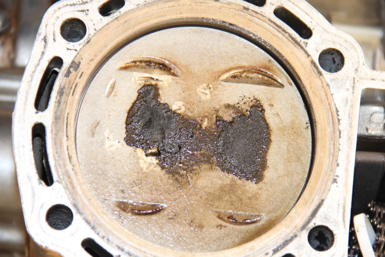
I worked with the motor on the bench today, my garage is dimly lit so videos were out. I was able to split the cases and take a quick look but I found no damage spots, I will look closer while cleaning up, along with double checking diagrams to ensure that I built it right the last time. The top of the piston and underside of the head had a lot of carbon build up for only 100 miles of service. A quick look as I was disassembling showed intact rings and a clean bore with no oil tracks. Then again the metal flake could have been residual from the original rebuild that just didn't get flushed properly. No problem I needed to address the carbon buildup problem anyway. What do you think Moses?

-
Kawasaki KLR Motorcycle Engine Teardown and Inspection
forman replied to forman's topic in Dirt & Dual-Sport Motorcycles
The right side inspection. -
Kawasaki KLR Motorcycle Engine Teardown and Inspection
forman replied to forman's topic in Dirt & Dual-Sport Motorcycles
Yes Moses you are right, and my hat is off to you for the video work you do. All the work involved in getting a video published is much harder that the actual work! -
Kawasaki KLR Motorcycle Engine Teardown and Inspection
forman replied to forman's topic in Dirt & Dual-Sport Motorcycles
Sorry I should have clarified that the photo was taken prior to the last rebuild. The engine was a wreck. a spring loaded tensioner is used in this 2006 engine. The engine is basically unchanged from '86- 2007. That isn't completely true I should say from '96 -2007 and possibly to the present model (I'm just not familiar with the generation 2 model that came out in 2008). -
Kawasaki KLR Motorcycle Engine Teardown and Inspection
forman replied to forman's topic in Dirt & Dual-Sport Motorcycles
It has been too cold to work in my garage so I've had some time to think about what I would like to do next. I'm looking for aluminum damage. The head is made of aluminum and I've yet to pull it off and look at its underside, but for some reason I feel confident that it is fine and that would cost me a gasket to check it out. The piston is made of aluminum, but I'm not ready to go there yet either. On KLR's the timing and cam chains are located on the left side, if you remember I mentioned that the vibration I felt was more of a buzzy type that a chain to metal friction area might produce. Armed with this bit of reasoning I will attack the left side of my engine when the weather permits. I will need to remove these side plates anyway if I need to go deeper into the crankcases. Here is a photo I took while tearing down the engine a few months ago that shows what I will be looking into.
-
Rebuilding a Jeep CJ-7 Dana 300 Transfer Case
forman replied to forman's topic in 1972-86 AMC/Jeep® CJ and Jeepster Models
What the heck here is the video. I had to apply pneumatic force for an extended time on both shafts but the process worked very well. -
Rebuilding a Jeep CJ-7 Dana 300 Transfer Case
forman replied to forman's topic in 1972-86 AMC/Jeep® CJ and Jeepster Models
I do not have nor do I have access to a bead blaster at least for the moment . Do you have any other suggestions that might help me clean these parts? I thought I would try to use the air hammer to push the shafts through their respective bearings... here is how I blocked up the case. I shot video of the air hammer removal but unbeknownst to me my camera went to sleep due to a low charge and the video did not capture the shafts falling through the case. Finally an empty case with input and output shafts.

-
Rebuilding a Jeep CJ-7 Dana 300 Transfer Case
forman replied to forman's topic in 1972-86 AMC/Jeep® CJ and Jeepster Models
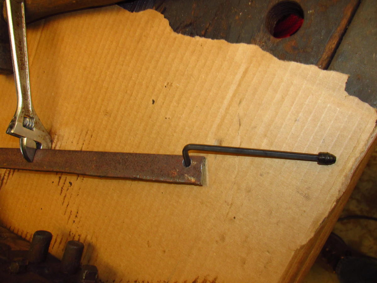
I know the one thing I did not want to do would be to round off the hex in the set screw. I think I mentioned in an earlier post that I live in the middle of nowhere and purchasing parts takes a few days. With an understanding that if I ruined the hex, then the removal of the shift arm and shift rod would be delayed probably until i cut the shift rod with a cutting torch. I decided to give the removal of the set screw the old "college try". I was limited by leverage so I made a simple tool and was certain that the alignment was straight. I have to admit that I was thinking of giving up when the set screw "winked" and then gave up and let itself be loosed. I think I'll get those tools on order now. The tool I made to help remove the set screw below
-
Rebuilding a Jeep CJ-7 Dana 300 Transfer Case
forman replied to forman's topic in 1972-86 AMC/Jeep® CJ and Jeepster Models
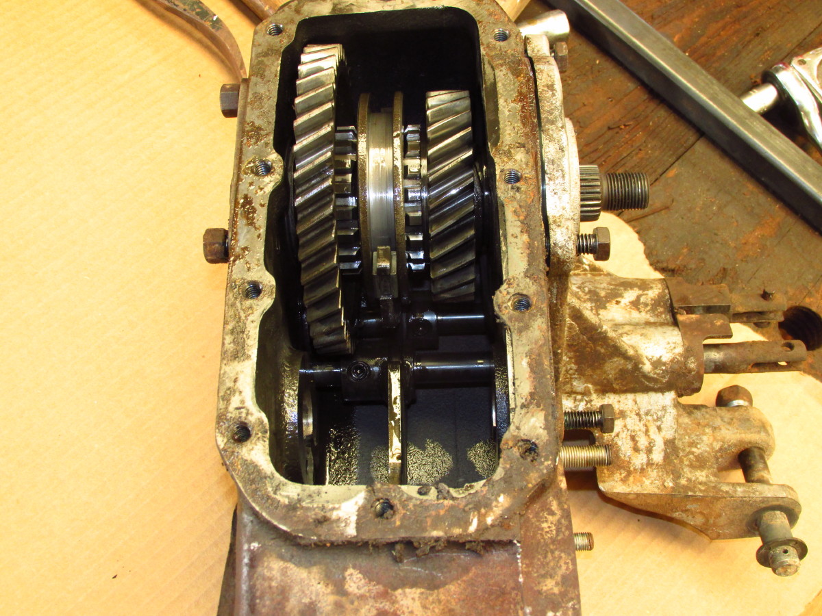
Just below the center of the photo are a pair of shift forks. I was able to remove the set screw of the rear output shaft shift fork and remove the rear output shaft fork shift rod. Quite a tongue twister say that 3 times really fast ... almost as difficult as saying "I'm a sheet slitter I slit sheets" repeated several times. However the other shift fork set screw does not want to be loosened with the tools I have. I think I will try some heat applied with a heat gun tomorrow. Then acquire a socket driven allen head if that doesn't work.
-
Rebuilding a Jeep CJ-7 Dana 300 Transfer Case
forman replied to forman's topic in 1972-86 AMC/Jeep® CJ and Jeepster Models
Moses those downloads are very important to me right now many thanks! I worked on the transfer case during my lunch break today I utilized a tip from the author of Jeep CJ rebuilder's manual. I used an air hammer with a blunt point to drive the rear output shaft through the rear output shaft front bearing. It took longer to roll out the air hose and oil the air tool than it did to push that shaft through the bearing. A very smooth operation! PHOTO 2 is of the rear section of the shaft after the rear bearing cap was removed.

-
Hey I enjoyed the compressor story! Today I was able to start disassembling the transfer case I followed your procedure and took some photos. The impact driver worked great on the yoke nuts and to be honest most of what I disassembled today was very easily done. I have to admit once I learned the new to me transfer case nomenclature it went very well, I'm having fun. I noticed that the intermediate shaft had some wear, I could feel where the gears rode on the shaft. The gear teeth that I can see so far aren't showing any sign of wear I hope some of the photos will show. In the first photo the bushing on the left looks rough on the outside.