


MikeBell81
-
Posts
4 -
Joined
-
Last visited
-
We finally got it running; it wasn’t the CKS but rather the timing mark on the balancer. We removed the balancer bolt to expose the crank keyway and discovered the pulley timing mark was at least 100 degrees off from where it is supposed to be. We went to the auto parts and measured the correct spacing, about 2.25” from keyway to timing mark, and created a new mark on the old balancer. We re-stabbed the distributor and it fired right up. Moses, thanks for your help. Mike
-
I just spoke to my friend after he reviewed my last post. He said it felt like the notches were closer together (not 20 degrees apart) like in the photo but the timing events were accurate. He also mentioned he thought the CKS wires looked a little damaged so he is ordering another one and we will see what happens when the new one gets installed. No need to reply to my last lengthy post.
-
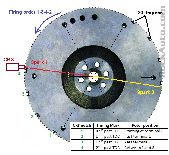
Hi Moses, Sorry for the delay, I had to go home and my friend lives 4 hours from me. I’m relaying messages to him and he is trying to find time for diagnostics. We have verified the timing mark on the balancer is within an inch or so of TDC when the piston is on the compression stroke for #1. It’s hard to find exact TDC on #1 with the head on but we are close. I’m working on a theory the balancer mark is off on the front pulley, which would cause the distributor to be in the wrong place. I had my friend monitor the location of the pulse generating notches on the flywheel compared to the harmonic balancer mark and the rotor in the cap. From what I’ve read there are 2 sets of 4 notches on the flywheel for the crank sensor and the coil fires on the training edge of the 4th notch, which is at 4 degrees before TDC. “The notches cause a pulse to be generated when they pass under the sensor. The pulses are the input to the PCM. For each engine revolution there are two groups of four pulses generated on 2.5L 4-cylinder engines. The trailing edge of the fourth notch, which causes the pulse, is four degrees before top dead center (TDC) of the corresponding piston.” I downloaded a photo of a Jeep flywheel and marked it up to show approximate locations of timing events. If you look at the table in the photo you can see by the time the 4th notch gets to the sensor we are way past TDC and the rotor can be firing either plug 1 or 3. The timing mark is about where I saw it when I was using the timing light on the number 1 plug. When my friend finds some time he is going to remove the balancer bolt to see where the crank keyway correlates to the timing mark on the outside edge of the pulley. I don’t know exactly how far apart they are supposed to be but from photos I’m guessing about 45 degrees. If it looks way off we can compare it to one at the auto parts store. Lastly we did verify proper grounding and we will check the sensor resistance. I will let you know what we find. Thanks, Mike
-
I just helped a friend install a rebuilt engine into his son’s 2000 Jeep TJ with a 4 cylinder 2.5L, manual trans and 4WD. He got the engine as a long block so we only had to reuse the tin covers, ignition and fuel systems. He got it from a reputable nationwide rebuilder so we are not concerned with dumb mistakes like timing chain installed incorrectly issues etc. We installed distributor as described in the service manual (TDC on 1 of compression stroke with 3/16 pin thru Camshaft Position Sensor and distributor housing etc.). The crankshaft position sensor is a two bolt type so no adjustment needed. I’m aware the PCM controls the timing so we can’t do anything with that. I’m assuming the CKP is working because we are getting flashes from the timing light. When trying to start the engine it kicks and bucks with an occasional backfire thru the throttle body. We connected a timing light to number one and looked for the initial timing around the marks on the timing cover but it appears the mark on the balancer is showing up at about 50 degrees after TDC. We have triple checked everything (firing order, sensor connections etc.) but can’t figure out how to get it running. We tried putting the PCM in learning mode by disconnecting battery and holding positive and negative together for several hours to try to drain the capacitor that keep PCM memory alive. We also did the ignition ON, headlights ON and then OFF, ignition OFF procedure. After putting in learning mode we disconnected the fuel pump fuse so we could crank the engine long enough for the CKP to figure out what is going on. Does anyone have any ideas on where to look next?
