


Moses Ludel
-
Posts
4,447 -
Joined
-
Last visited
Content Type
Profiles
Forums
Blogs
Store
Articles
Gallery
Posts posted by Moses Ludel
-
-
Welcome to the forums, Diamond Jr...Could you please add a couple of photos to illustrate your "problem"? I'd like to see the release bearing in the extended and retracted positions that you describe. "90%" onto the retainer would be unacceptable if you mean that the bearing does not fully slide onto the sleeve/tube.
I'm assuming that you're using the release arm, slave cylinder and master cylinder that work with a '95 bellhousing? The four-cylinder engines do not use the shim/plate between the block and bellhousing, but you do use a dust cover at the lower section of the bellhousing.
You can post the photos here at this topic, and I'd be pleased to comment on what you're encountering.
Thanks!
Moses
-
JohnF...Could very much be stock springs for 1970. The "turn down" is to eliminate spring leaf friction. More modern springs use nylon inserts at the ends to accomplish this. The aim is to prevent premature damage to the leafs from rusty, dirty spring ends digging into the adjacent leaf.
You've seen that pattern in worn old springs. As you discovered with the loosening of the plates for spring bolt replacement, the natural curvature of the spring leaf creates abrasive angles at each leaf end. This presses into the adjacent leaf when the springs stretch out and the leaf ends curve inward.
As many of us have discovered, Jeep was poor at illustrating parts in both the factory parts manuals and the service manuals. Jeep was also inconsistent about parts sourcing and model year changes for parts. Parts often got carried over from previous models and actually do not "match" the year of the vehicle. Clear changes take place between major model shifts, like the 2A/3A/3B (MB/M38) to CJ-5 (M38A1), or the Kaiser era changeover to distinct AMC/Jeep models in 1972.
If these springs have the correct length and width, are not broken leafs or beyond rebuilding, and if the price is right, there is nothing "wrong" with leaf springs that will not chafe between the plates. The curved ends, in themselves, do not present a problem if these springs are the correct length, width and spring rate.
Moses
-
Interesting...Is this a splined coupler or a slip yoke? If a splined coupler, even if you did not separate the spline section, you might have an issue with spreading or thinning the OE grease by extending the coupler and returning it to the normal/operating position. Please clarify whether this is a splined coupler or slip yoke. If migrating grease was an issue, it sounds like a slip yoke...
On aftermarket shafts with splined couplers, a special "coating" on the splines often acts as a friction barrier. This is typically blue in color, and you've seen it on custom drivelines with splined couplers. As for slip yokes, a spline matchup with the original position is seldom considered, and unless you carefully mark the slip yoke and transfer case output splines, there's very little likelihood that the shaft will end up at the original spline alignment. Repositioning the slip yoke on the transfer case output splines would seldom create an issue unless there is abnormal spline wear on either the coupler or the output.
Of course, with a splined slip coupler, you must have the driveline's U-joints aligned or "in phase". When a splined slip coupler is taken apart and reassembled, the U-joint and flange position at each end of the driveline must match and be in alignment. Additionally, with a balanced driveline, these matched positions must also be consistent with the position of each U-joint flange when the shaft was built and balanced.
Moses
-
Are your original springs beyond rebuilding? They are 39-5/8" length, right? Could the shop rebuild it for the same cost as the CJ-2A/3A springs?
Moses
-
Welcome to the forums, nbruno! I am at Moab EJS (not at my shop/studio) and would like to explore the Davies Craig water pump further. I took a quick look at the corporate site, and the electric water pump is interesting. I would like to research the longevity (duty cycle) of the electric motor when running continuously or thermally activated. It would run continuously in a warmed-up engine in all likelihood, and engine coolant heat is substantial.
Also, re-routing the belt to stop turning a squeaky mechanical pump is suspect. The parked impeller could create a blockage of flow. I would like to know the problem with the OEM water pump. Is anyone making an OE mechanical water pump that does not create trouble? On that note, is the problem squeaks or actual bearing and eventual seal failure? Squeaking can sometimes be strictly belt and pulley related.
Please share what you know. I'm glad to research further so we can determine a sensible remedy...
Moses
-
The 2A and 3A have an 80-inch wheelbase, the M38A1 and CJ-5 introduced the 81-inch wheelbase. This is a clue.
Were your original springs broken? Why were they not the ones you had rebuilt?
Trust you will find a buyer for these flat-fender era springs. Advertise them and include the main leaf length (typically eye center to center) to be sure the springs will fit before shipping them to the buyer...The price is right, you had the springs rebuilt by a reputable shop. Add freight to your cost for the 2A/3A springs plus rebuilding charges, and you'll have your investment back, JohnF!
Moses
-
I'm trying to imagine an engineering need here. The available transmissions did not require this drop. Did the bellhousing require a drop to clear the firewall? Does the V-6 225 engine set lower than the centerline of an F-head four-cylinder? How is this related to the Buick V-6 option? Exhaust clearance for the V-6? Something that requires lowering the back of the engine? The distributor is conveniently at the front.
Dropping the rear (engine/transmission) cross member may explain the rear axle wedges, too, although dropping the transfer case should decrease the U-joint angle at the front of the rear driveline. That would require tilting the rear axle pinion upward to achieve a complementary (cancelling) U-joint angle to match the rear driveshaft's front U-joint. Which way did the wedges originally face?
Moses
-
You know the history of the Jeep, JohnF, so presumably these are OEM origin. The reason these are used is to rotate the axle and adjust the pinion shaft/U-joint yoke for proper U-joint angles at the rear driveline. On your vintage V-6 Jeep CJ-5, the wheelbase is only 81". The rear driveshaft is short and susceptible to vibration and damage if U-joint angles are not "spot on" and cancelling each other at the rear driveline.
I had a lengthy discussion with Megatron about U-joint angles, and you'll find it helpful for understanding the use of these wedges. Jeep was trying to match the angles at each end of the rear driveshaft, which is correct for a shaft with a single-Cardan (cross) joint at each end of the driveshaft:
My response at the later posts provides details...For the rear driveshaft, you're striving for matching U-joint angles with the vehicle at ground/curb static height and normally loaded. The single Cardan joint angles should cancel each other in that mode. The wedges are used for changing the U-joint angle at the rear axle to match the transfer case joint angle.
Moses
-
Yeah on the AX15 rebuild, great job, TTippetts!
Understand the Jeep J10 dynamic and why the TBI 350 V-8. Though less horsepower than an LS, these engines produce excellent torque, which you probably want anyway...Many GM Suburban 4x4s with the 350 TBI lugged larger travel trailers with the right axle gearing.
We had an '87 K2500 (cargo doors and 4WD, Federal emissions) and really valued that rig and its THM400 behind the TBI 350 V-8. Last heard, the truck has clocked over 300K miles on the Mr. Goodwrench crate engine installed before we bought the Suburban at 140K miles. Original owner had used Mobil 1. I kept the engine on Mobil 1, and it's still running on Mobil 1 for the friend that bought the truck at 180K miles!
Please keep us posted on the J10 project and developments, that section at the forums could use your input and findings!
Moses
-
Interesting video and comments...The added foam "jetting" change seems two-fold, first a "choking" of air flow through the restriction, and secondly, according to the YouTube presenter, a possible offset of what he calls "reversion" air flow.
The first factor is much like the claims of aftermarket air filter companies that boast "less restriction", only in this case it's the opposite. I've changed back to a stock air filter and even added the missing OE anti-backfire screen, an additional air restrictor if you will, to the Honda XR650R motorcycle. While "uncorking" these Big Red Pig models involves removal of the stock air box restrictors (done by the PO, none in place), actual filter air volume is a measurement of CFM flow and the filter's surface area.
I'm banking on Honda having enough sense to provide adequate air volume through the stock filter and the vital OE anti-backfire screen. (Many remove the screen for more flow. Envision the bike on its side with fuel flooding out into the air box. This is a major fire hazard with the anti-backfire restrictor removed!) I only re-jetted to what is actually stock on all non-U.S. market Honda XR650R cycles with this same carburetor, compression ratio, etc. This was the conservative approach, and the HotCams Stage 1 camshaft should be okay with that jetting, too. Stock jetting for the non-U.S. market is 175, I went for 172 at our altitude and mountainous, high desert riding environments. I'll see whether the stock air filter creates any kind of enrichment factor.
Note: RPM plays a role in the main jetting needs. I'm not "racing" this motorcycle nor redlining the rpm constantly. In fact, I need to conserve fuel at my remote riding venues and make sure this engine stays intact and reliable.
What I'm hinting about is that filter surface area (or a foam restrictor like this video describes) would simply control air flow volume. So does the choke or a dirty air filter for that matter. The engine's air requirements are based strictly on CFM requirements for the cylinder displacement, camshaft valve opening duration and lift, and the valve timing "events" as the video mentions. The OE carburetor, at least theoretically, should have the right CFM flow for the engine. My XR650R uses a 40mm Keihin, no CFM rating to share here.
CFM flow of a carburetor is based on the engine speed as well. Jack Clifford, an inline six devotee, and I discussed Jeep 4.2L six-cylinder requirements years ago, and he threw out a carburetor formula: 1 CFM for each cubic inch of displacement to run the engine at 4,000 rpm. More rpm, more CFM flow required. Many sport bike motorcycle engines are barely on the throttle at 4,000 rpm.
So, assuming the engine has the right carburetor, and an unrestricted air filter of the correct surface area to match the CFM needs for the carburetor and engine, there's still another factor: the air box flow. This is a science, and latent horsepower is often found in a redesign of the air box, affecting the air flow and velocity to the carburetor or throttle body intake. The filter, in combination with air box flow dynamics and air delivery changes, can dramatically impact performance. There is an entire automotive aftermarket devoted to these performance improvements. OE air boxes are often misshaped to meet fit and engine bay requirements, and so forth, restricting the performance of the engine.
The presenter mentions "reversion flow", and as he describes it, that would be a function of camshaft design/lobe profiles, valve timing and engine speed, manifold vacuum and the induction system design. He may be right on with the reversion taking place, and that could be a factor of air box placement limitations or even air box tuning to deliver a certain kind of performance at a given engine rpm. This tuning could be performance and/or marketing driven.
The "foam jetting" is a restriction of air flow volume at the filter. If the engine is getting enough air (CFM flow) with or without the restrictor foam, jetting should not be impacted. Although the blockage alters the engine's ability to access air, that does not necessarily mean the engine is not getting enough air. Choking the engine with the choke valve is entirely different: The choke valve restricts the incoming air and also raises the vacuum/fuel draw from the carburetor idle and pilot circuits (enriching the mix further)—while at the same time restricting incoming air (CFM) volume.
Not sure whether the bike in the video is carbureted, but I'm assuming that's possible by the mention of "jetting". If the cycle had EFI with an oxygen sensor regulating the A/F ratio, regardless of intake air flow restrictions, the A/F ratio issue would be moot. A Jeep engine with MPI will adjust A/F even for a dirty air filter. A/F must remain constant to meet emission requirements, and the engine and vehicle simply will not perform well with the lessened air volume: Injector fuel flow gets lowered to match the available air. That's the beauty of EFI/MPI versus a carburetor, the EFI adjusts for altitude changes, available fuel and air, manifold vacuum and barometric pressure.
By contrast, the alteration of air intake flow, air velocity or air volume into a motorcycle engine with a carburetor can have a distinct effect on jetting. The video implies that the air box in question actually flows more air than useful. If the engine runs better and does not show signs of excessive enrichment (blubbering, fouled plugs, blackened exhaust soot and such), then it's getting improved flow or simply running richer and obviously better than stock.
Forman, keep in mind that later EPA requirements for on- and even off-road vehicles, including motorcycles, demand the leanest A/F mixes tolerable. Restricting the air box intake with foam, as illustrated in the video, might be just enough to enrich the mix slightly while still allowing enough CFM flow to meet the engine's requirements. This could be the source of happiness for the engine...You'd have to do a four-gas exhaust analysis, with the motorcycle on a dynamometer under various loads, to see what's really going on here.
Moses
-
JohnF, the spring centering bolt heads must reach through the wedge spacer and catch the axle spring perch hole. This is how the rear axle stays in alignment. It also helps hold the wedge in position.
Especially with the wedges, any movement or shifting of the axle housing/perches will allow the U-bolt nuts to loosen. The wedge(s) will be loose, and the axle can shift out of alignment. Dangerous looseness of the spring U-bolts and hardware will result.
You can find spring centering bolts with deep heads, the length you need. To save time, you can also very carefully double clamp (large clamps!) the spring leafs together near the center bolt before changing out the spring center bolt. An option would be a large vise as a holding fixture, perhaps with a set of C-clamps as a safety backup.
Do not let the leafs loosen, this could misalign the center bolt hole. You would struggle to get leafs back in alignment. The shop that rebuilt the springs has access to center bolts like I describe. These are essentially the same bolts you have now only with taller heads of the correct diameter and height for the wedge and perch holes.
Moses
-
Congrats, Forman! Great work and thanks for the compliments on the Jeep CJ Rebuilder's Manual: 1972-86. The book will be very helpful with any of your other endeavors around this CJ-7.
I'm finding HD video increasingly more effective as an instructional tool. Want to add "time-marking" and indexing so folks can jump back and forth to specific points within a how-to video—like we do with a print book. I've set up the shop/studio for detailed tech in high definition video. You'll see the first clearly HD product in the Honda XR650R top engine assembly video I'm now editing...
Moses
-
Thanks for the comments about the L.A. Sleeve work and video. The upper engine assembly video will be available shortly.
Forged pistons are generally higher compression ratio. The material is intended for severe duty pounding, typically in a racing environment. The expansion rate for forged alloy pistons is such that the piston-to-cylinder wall clearance must be wider, and these pistons can be noisy at cold start and require warming up the engine to quiet the pistons down. Newer design forged pistons, in some applications, are less noisy.
Cost for forged pistons can be high. Cast pistons are generally OEM replacement. On automotive applications, I most often use Silv-O-Lite (United Engine) hypereutectic pistons, which are technically "cast" but offer much better service and longevity. This is a good choice when forged pistons are overkill for the application, compression ratio and intended vehicle use.
For the Honda XR650R, I consulted with L.A. Sleeve about the quality of the L.A. Piston Company replacement piston. It is essentially an OE replacement piston, LAPC's "Pro-Cast" design, built to close tolerances to last at least as long as the OE piston, which holds up quite well with normal use. Add to this the precision machine shop honing and a quality ring set, also provided by L.A. Sleeve, and I am certain the setup will last a very long time. If I thought a forged piston would last longer in my intended use of the motorcycle, I would have opted for a forged Wiseco or similar quality piston and matched rings.
One concern that pops up in any case is engine operating temperature. A forged piston could tolerate extreme heat, and since I did stick with the OE equivalent cast piston, my focus will be improving the engine's cooling ability. Before getting overly concerned about the piston material, I am reminded that my earlier air-cooled Honda XRs (an XR350R and the XR500R) each use a cast piston and have survived Nevada desert riding year 'round for decades. The Honda XR650R motorcycle engine has 10:1 compression (stock) and liquid cooling. It will hold up very nicely with a cast piston.
Moses
-
Smart move with the "decorative" rivets! That should work. Welding the cross member into place makes sense when done properly...Hot riveting is difficult to do in this day and age, the equipment is long gone. I wonder whether you could do a hot rivet with a carbon arc welder.
Thanks for sharing and keeping us posted, the reworked springs look great!
Moses
-
Congratulations, TTippetts! Great job there...The J10 sounds intriguing, likely you passed on an AMC 401 or 360 V-8 buildup for cost reasons. The AMC engines have become very spendy to rebuild! The small-block 350 Chevy V-8 has been a logical mainstay, and a TH350 should work well, too. Did you consider a later LS engine? Cost should be coming down on recycled GM truck engines.
Keep us posted. Pleased that your AX15 is back together and performing as new!
Moses
-
Read my reply at the General Repairs and Technical Tips topic: http://forums.4wdmechanix.com/topic/295-how-to-hone-an-engine-cylinder/. Also, take some "Forman" photos and accurate measurements of the cylinder you plan to hone. Share these details at the "How to Hone an Engine Cylinder" topic. I'll provide further tips based on your findings and photos.
You can do this, Forman!
Moses
-
First, it's all about piston to wall clearance and ring end gap measurement. These must stay within the manufacturers' guidelines for acceptable limits.
Years ago, in automotive circles, rings were commonly available for in-chassis engine overhauls or "ring and valve jobs". Perfect Circle, I recall well, had piston rings to fit 0.000"-0.010", designed for the OE standard size pistons. Filing ring end gaps to size was common practice if a bore was only slightly oversize and the new ring end gaps were too close. This approach worked okay for "in the day" engines to 8:1 compression ratio that ran with 160-180 degree F thermostats.
When ring gaps are too narrow, there is no room for normal gap changes at different cylinder wall and piston temperatures. Gaps too narrow, and the rings can actually seize in the cylinder. My tools include two hand-operated ring gap filing fixtures, and I've used modern power files on custom ring sets (packaged without sizing) for high performance engines. Typically, new replacement ring sets for popular bore sizes or oversizes are accurately gapped from the factory. Filing rings is a rare need today. If you buy standard or oversized rings to match the piston size, the ring gaps should be correct if the bore diameter is accurately on measure. When in doubt, measure the ring gaps with each ring or spacer level in the bore.
The issue today is that manufacturers and consumers have shifted to "remanufacturing" of exchange engines or a rebuild at the local machine shop. In the process, an engine block is always bored and finish honed, and the standard U.S. automotive oversizes are 0.010", 0.020" and 0.030", sometimes to 0.040". (Similarly, metric oversizes typically run .25mm, .50mm, .75mm and 1.00mm.) This has become so common that the "reman" shops like to bore every first-time go around U.S. block to 0.030" if possible. Tooling can be readily adjusted and pistons for this bore size cost less at the wholesale level. Today, the other oversizes are often special order.
Caution: 0.060" or larger bore sizing is considered a high performance approach for blocks that do not have core shift or thin walls. I recommend ultrasonic testing of cylinders before considering 0.060" oversize on a Jeep 4.0L inline six block. Ford "351M/400" V-8 blocks are notorious for core shift and should be ultrasonic tested for boring even to 0.040" oversize.
For motorcycle and automotive engines, slight honing should stay within end gap norms for the new piston rings. The piston to wall clearance measurement should also indicate whether or not you've exceeded the ring gap limit. If you have too much clearance, you'll need to bore the cylinder(s) for the next oversize piston and ring size. Typically, the two measurements coincide, so if you use the OE piston as a measurement baseline and come up with acceptable piston-to-wall clearance after honing, the new rings for that bore size should also have acceptable ring gap measurements.
Footnote: Forman...Hone and do the piston measurement before ordering new rings or a new replacement piston for your Kawasaki KLR thumper motorcycle engine. What size rings are available for the KLR650 engine?
Honing should not remove much material. If the cylinder has too much taper, it's wise to re-bore and machine hone for the next size piston and rings. If there is noticeable taper, the traditional approach is to carefully cut the area above the taper with a ridge reamer and remove the ledge. That cut ridge diameter, once honed with the rest of the bore, becomes an appropriate point for measuring the piston-to-wall clearance.
Note: If the engine block or cylinder can be honed after cutting the ridge, a stone hone would be mandatory for truing and uniformly sizing the bore of the cylinder...If there is significant cylinder taper and a noticeable ridge, the added cost of machine shop boring and fitting of an oversized piston(s) and rings would be advisable. I refer to "cylinder(s)" because our members and guests range from single cylinder motorcyclists to V-8 and V-10 automotive/truck owners. If you need to resize any one cylinder in a multi-cylinder engine, you must resize all cylinders to the same oversize. Matched new pistons and rings in that new size would be mandatory.
Minor honing with a drill motor is typically limited to engines with very light cylinder wear and the need for seating and sealing a new set of rings. For motorcycle engines, especially two-strokes, it is not uncommon to have a bore size still within tolerance, both before and after honing, with the installation of a new piston, pin, circlips and rings. This is especially true with Nikasil plating. After cleaning, if a Nikasil bore looks unblemished and still shows a strong cross-hatch pattern, leave it alone. If there is a need for honing a Nikasil cylinder, I strongly advise having L.A. Sleeve Company or a similarly qualified machine shop perform that work.
Moses
-
Craig, thanks for the compliments! The links I provided cover a lot of ground with the troubleshooting and understanding the functions and identities of the various Jeep 2.5L TBI components. Our forum exchange was a hands-on like yours, and some wading through the materials should provide insights. Of course, I'm pleased to go further if you exhaust the details offered and haven't solved the problem!
You mention the wiring harness splicing and butt connections, and that is a concern. For EFI sensors, the important signals for the ECU are dependent upon wires with integrity and the correct resistance. Butt crimp connectors are terrible when resistance is critical: There is no assurance that all strands of the wires will make contact. There's also the risk of moisture wicking into the connector and up the wire insulation, a problem that worsens with humid climates, 4x4 water fording and even the occasional clean up at the car wash! Crimp connectors work for trailer light wiring and other tasks where resistance loads are not critical—just step up wire gauge and use the right fuses!
Also, you described the sensors looking like mud and acid. Shorts to ground or voltage leaks to ground can result. Like a dirty battery case, if the sensors are encrusted with conductive material, and that can include soil with minerals, there could be voltage leaks to ground. The terminal of a sensor could be shorting mildly to the brass or metal shell of the device and creating resistance or voltage changes. Even minute voltage changes can throw off a sensor signal to the ECU.
If you cannot find harnesses or a harness change-out appears daunting, you can repair wiring properly and get good results. I like to use rosin core solder and seal the solder joints with multiple layers of heat shrink tubing.
First, I place fresh heat shrink tubing, cut to the right lengths, well up the cut wires and away from the soldering heat. Take the stripped, opposing wire ends and interlace the bare wire strands together—facing toward each other. Minimize the diameter of the bare wire joint; mimic the diameter of the insulation if possible.
Now you can solder the braided strands together, using rosin core (not acid core) solder. Add rosin paste as desired to assure solder flow through the bare wire strands. A finished solder joint around 5/8" in width works well, using a smaller soldering iron or a soldering gun.
After the solder joint cools, slide the heat shrink tubing over the bare soldered joint and insulate the section. Shrink the tubing carefully to the wire insulation without melting the insulation. The tighter the tubing against the insulation, the better seal. You can double up with a couple of heat shrink layers...Done correctly, heat shrink can prevent shorts and moisture wicking.
Note: To shrink tubing, I use a heat shrink gun, heat gun or even wooden kitchen matches with the flame passed quickly around the tubing without melting the wire insulation or burning a hole through the tubing. Practice on an old scrap of wire.
Soldering takes time but can save wiring and make permanent repairs. Unless the current damage is extreme, avoid replacing harnesses. I like your approach: Restore known wiring issues first. Later, the troubleshooting will be accurate and reliable—like you want your Jeep Wrangler to be!
Keep us posted and share interesting developments. Troubleshooting will be straightforward once the wiring is in good shape.
Moses
-
Great post, Rocket Doctor!...My only trip to Alaska so far was in 1975. I was working at construction in Carson City, Nevada, and given a moment's notice offer to make the drive. My good friend, Bob "Bearclaws" Stuttsman, was the impetus for that trip. (I shared details about Bearclaws at the forum: http://forums.4wdmechanix.com/topic/149-outdoor-friends-family-and-mentors/?p=485.) Bob was as colorful as the trip itself!
We drove from Carson City straight up U.S. 395 to Colville, Washington and crossed the border at the base of the Okanagan Valley. Bob couldn't stop talking about U.S. gun laws as he "allowed" Canadian Customs to secure a customs string and seal around the metal tackle box that housed his two .44 Ruger single action pistols. Canadian Customs could easily have told us to make a U-turn with the '66 I-H Travelall 4WD and our small travel trailer in tow. Instead, the tolerant official simply said, "We understand your gun laws, but this is Canada...This seal must be in place when you exit Canada at the Alaska Frontier...Here's the accompanying paperwork, Mr. Stuttsman."
In those years, you could transport pistols in a customs sealed container. We each had long rifles that were declared at Customs, and there was no concern about hunting rifles. Bob had his Model '86 Winchester 45-90, I toted my 1908 vintage Winchester nickel-steel octagon barrel .30 caliber, each were traditional lever action rifles.
The Fraser River, Fort St. John, Ft. Nelson and Whitehorse were each memorable. Along the Alaska Highway, a stop at the Liard River Provincial Park is a must. (Here's a quick Wiki overview: http://en.wikipedia.org/wiki/Liard_River_Hot_Springs_Provincial_Park.) After days of dirt travel (1100 miles were still dirt in 1975, this is Milepost 497), the public hot springs make a welcome break. Moose, wolves and bears are plentiful in that area.
I took photos on that trip. In our living room are framed prints of photos taken alongside the Liard River at sunset and near Tok Junction, our entry point into Alaska. The prints have weathered nearly forty years of shuffling from home moves. The camera was my bulky Mamiya-Sekor C330 twin reflex 2-1/4" square format. Rocket Doctor, you'd enjoy the photo of a moose cow in a marsh near Tok Junction.
Bob and I headed through the Matanuska Valley and past Fort Richardson en route to Anchorage and the Kenai Peninsula. Bob's Cousin Ned lived at Soldatna, he had homesteaded there with his brother in 1959. A failed potato crop drove Ned into a job with the local school district. We spent time on the Kenai and drove out to the spit at Homer, where I took photos of the King crab catch at the local docks.
My trip back to Carson City and an apprenticeship with Local 3 of the Operating Engineers began with a puddle jumper air flight over the Cook Inlet to Anchorage...I flew from Anchorage through Seattle to Reno with reflections of Alaska the entire way. Bob stayed on at Ned's place for a bit, scouting out the Kenai as a possible move from Nevada.
Our trip was the first two weeks in September, the same time you were there, Rocket Doctor! Mosquitoes were not totally obnoxious, and it was a remarkably colorful season...
I would enjoy another Alaska trip. This time, I'd make a right turn at Tok Junction and head for Denali and Fairbanks. Maybe on a dual-sport motorcycle, though I'd avoid overnight tent camping in bear country! It's one thing to sleep in a tin trailer with two rifles close at hand, another to sleep just a nylon tent wall from a grizzly!
Moses
-
Great, Megatron! Your truck deserves to be free of shudders...
When the U-joint angles are different, opposing joint rotational forces work against each other. Envision the angled arc that each U-joint follows as it rotates. Since part of the joint "compresses" and the opposite side "expands" during each rotation, there is actually a speed-up and slow down over the arcs. The driveshaft/joint input and output speeds remain the same; the U-joint design compensates for speed variations during each rotation of the joint.
Simply put, if the rear driveshaft's front U-joint angle differs from the rear U-joint angle, even if the two joints align properly in "phase", they have irregular speed-up/slow down patterns over their arcs of travel. So you get a vibration because the shaft is fighting itself end to end. Another cause for this vibration is when a splined driveshaft is assembled with the cross-joints misaligned. This is "out of phase" and a real cause of vibration. It can even tear apart the driveshaft since the speed-up and slow down over the U-joint arcs of travel run at different cycles.
You mention power/torque, and that brings up another concern. A driveshaft loses torque capacity as the angle/slope of the shaft increases. When a vehicle gets "lifted", the typical 4x4 scenario, if the driveshaft slope increases, the torque capacity of that driveshaft diminishes. U-joint life suffers, and failure of joints is often common. Even when the U-joint angles match as they should (by shimming the pinion angle or mid-shaft bearing properly), the U-joint lifespan is shortened. This is strictly a function of U-joints: steeper angles make the joint weaker.
One way many offset this risk is the use of a CV or double-Cardan joint at the transfer case output yoke and a single Cardan joint at the rear axle pinion yoke. The CV not only reduces the angle on each joint within the CV assembly, it also helps knock off the driveline slope factor considerably. Since the double-Cardan CV joint has "self-cancelling" angles between the two cross joints, the rear axle joint angle (a single Cardan cross joint) can be very close to straight when measured at static vehicle height—with axles weighted or on the ground.
Actually, 0-degrees of U-joint angle is unacceptable for U-joint survival. When running a CV driveshaft, I set the rear axle pinion joint (single-Cardan) for 1.5- to 2-degrees angle with the vehicle at static curb height and weighted. This minor angle allows the joint's needle bearings to rotate in the bearing caps, which prevents them from starving for lube and also distributes the load uniformly over the needle bearing sets within the U-joint caps.
Note: The 1.5- to 2.0 degree rear joint angle is achieved by rotating the axle housing to angle the pinion shaft and yoke upward. There is only one "downside" to doing this: Lubrication/fill of the differential is thwarted by the dropped fill plug height. Aftermarket differential covers for lifted trucks often have a relocated fill plug, higher on the cover to permit normal fill levels with the pinion angle rotated.
The amount of rear axle rotation has little affect on chassis geometry or spring action. Many lift kits provide a tilting spacer block to restore U-joint angles. On installations that require use of spring-to-perch wedges to restore the rear U-joint angle, I use steel and not aluminum wedges. Steel will withstand more punishment and not pound out or loosen over time.
Thanks for letting us know how this worked out, Megatron! Great to hear your Ram is back in top form...
Moses
-
Paul...I'd cleave toward the Canadian readout of 7,297 pounds, still less than I expected. The tires are stock size and like my '05 before the change. You're running a lot of pressure when empty, so they have more than enough air. (Are you okay with running this kind of pressure empty, or do you drop down to door sticker settings?) Sounds like you're pulling good size trailers but not pushing "billboards" down the road as far as wind resistance goes; the tall 5th wheels are the billboards.
Would like to hear if the gear ratios on the axles are other than 3.54:1. Glad you're into the pyrometer. When running aftermarket programming and these kinds of loads, you do need the EGT monitoring to keep a lid on the engine stresses. EGT is the best means for monitoring the load on a diesel. I need to get a pyrometer for the '05.
Really would like the dyne results from the community college testing, how fortunate that you can use this dynamometer. Stock would make sense as a baseline. This is exciting, Paul!
The 25 mpg is not out of reason for a 2WD empty with the correct gearing. If he drives like we do, for mileage, 25 is conceivable. I place great stock in the right gearing, the Cummins ISB engines are hypersensitive to rpm when it comes to fuel efficiency. Under commercial loads (to 50K GVCW, apparently a medium duty truck application, not my one-ton with a 48RE transmission, for sure!), Cummins would like to see the ISB engine running in the 2100-2400 rpm range. I wouldn't expect more than 17-18 mpg unloaded and 14 mpg pulling a 7,500# trailer at that rpm. When I push to 2100 rpm empty, which is actually my presumed torque peak with the Hypertech Max Energy programming, I can expect 19-20 mpg, depending upon terrain and wind.
This last factor, wind, cannot be underestimated. I raised the truck 4" with a chassis lift and added oversized tires, which is clearly a red flag for fuel efficiency. These trucks are hardly aerodynamic to begin, and I asked for it with this move. Since all modifications to my truck were made simultaneously, there is no way to separate the impact of the lift and broader frontal area, i.e. increased wind resistance, from the rest of the changes.
For that reason, I work with the known factors: 1) driving for efficiency is something I can control, 2) gearing is intended for a top speed of 69-70 mph if fuel efficiency is primary, 3) gearing (4.56:1 with 34.6"/35" tires) was picked to maintain the lifespan of the engine first, as a fuel mileage consideration second, and 4) I take full responsibility for the impact of the lift, tires, gearing and all the accessories added to the truck! This last point is an important qualifier. I can't complain about fuel mileage after doing all of these modifications intentionally. I'm in damage control mode at this point.
Let's keep working on your mileage. I appreciate your approach and the information gathering that you're willing to do. We can work with these facts and find a sensible strategy.
Thanks!
Moses
-
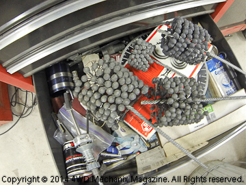
When you find that your engine repair includes cylinder honing, apply this process properly. The optimal honing finish will have the right cross-hatch pattern with correct angles. If you're unsure of the right "look" or angles, look closely at the photo below, the magazine's cylinder barrel after machine honing at L.A. Sleeve Company:

Hand honing will involve the correct diameter stone hone or flex hone ("glaze buster"). Your cross-hatch pattern will depend upon the right pressure and speed of the hone as you run it up and down in the cylinder. At our tools forum, you will find my comments on the two most common cylinder hones and their applications.
Once you choose the correct hone and decide what you want the cylinder wall to look like when finished, clean the cylinder carefully and take measurements. If you're honing in an automotive engine bay with the head off and the rods and pistons removed, make sure to protect the crankshaft journals from honing debris. This debris is abrasive and will instantly damage new rod and main bearings! Wrapping the journals with clean shop rags is one method of protecting the crankshaft.
I like to use a suitable honing oil. Some will use an actual machine shop honing oil. I like "Lube Guard Assembly Lubricant" for its lubricating and cleaning ability. As you hone, the cylinder must slough off abrasive from its pores. There is both the cylinder material and the hone material to consider here, each highly abrasive!
When honing, I like to use a rhythmic pattern up and down in the cylinder, moving the hone uniformly and with the same speed and force over the full cylinder. In the day, my mentors recommended moving the hone "in slowly, out quickly", and that pattern is good, too. If you're unfamiliar with the speed of a hone, try a one-second-down, one-second-up kind of count that's easy to follow. I use a 1/2-inch hand drill motor with cross handles if possible to maintain center while honing.
Note: For some motorcycle barrels, it might be practical to use a drill press and suitable holding fixture for the barrel. Simulate the honing equipment found in an automotive machine shop. You have good speed (usually adjustable on most presses) and alignment control. Set speed to your needs. Use plenty of lubricant while honing this way!
With a stone hone, you can adjust the stone pressure against the wall and also choose a suitable stone grit. If you have no idea what grit, there are usually manufacturers' recommendations for each stone set type. These are general recommendations and reflect speed and pressure as well.
Cylinder wall material can vary widely. Iron is often alloyed with nickel or even chromium and moly like L.A. Sleeve Company's "Moly 2000" liners. If in doubt, use a moderate grit, it may take longer but will not chew up a cylinder wall and require re-boring.
Warning: Both automotive and motorcycle engines that have Nikasil bore plating require special honing with a diamond hone. Do not attempt to hone this material with a conventional stone hone or glaze-buster silicone flex hone. Sublet honing to a shop with appropriate equipment.
A good approach when determining a cross-hatch pattern is to match the original cross-hatch that is evident at the top of the bore above the taper. This ledge or "ridge" is not affected by the piston ring travel and therefore should show a pattern that the engine manufacturer (or a machine shop rebuilder) has used.
Note: This works fine for most honing jobs, although there are some very exotic OEM hone patterns like the late '80s to 1990 4.2L inline six AMC/Jeep engines. Jeep had a problem with ring seating (likely due to consumers having no idea how to "break-in" an engine by that era). AMC went to a radical "swept" hone pattern: course, irregular and circular—not the conventional "X" look of typical power honing.
The simplest ways to have a new hone job go sour would be failure to thoroughly clean the cylinder of debris after honing and failure to sufficiently break-in or "seat" the new rings. I tested many Jeep and other 4x4 trucks for OFF-ROAD Magazine in the '80s to mid-'90s (Argus Publishers days) and also tested vehicles on behalf of the Portland Oregonian newspaper in the early '90s. I recall several tests involving vehicles with very low miles on the clock that were using/burning oil. The cause was previous testers running these engines too hard without consideration for break-in. I never reported the oil consumption in these vehicle evaluations; this was driver error, not a manufacturing defect.
In particular, I recall a 1989 Jeep YJ Wrangler with a 4.2L carbureted inline six that used a quart of oil every 50 miles and also a TBI Chevrolet Silverado V-8 pickup that used a quart of motor oil every 300 miles. Each of these engines had rings that had not seated. I was able to reduce the oil burning dramatically during my test intervals by simply treating these near-new vehicles with consideration and allowing the rings to seat properly. If given enough time, I'm certain the oil consumption could have been overcome.
Some practical considerations include selecting piston rings designed for a reasonable break-in period. Unless building an all-out racing engine with forged pistons, I avoid "chrome" rings. Moly rings work very well and respond quickly to a properly finished cylinder wall.
Make sure your cylinder(s) is spotlessly clean before applying either a light engine oil or Lube Guard to the cylinder walls for both piston and ring insertion and the initial engine startup. A new oil pump and pickup screen is always wise for automotive engines during a rebuild. You have the oil pan down anyway, replace the pump. For domestic engines, I've always run a Melling "High Volume" replacement pump and screen. Cheap insurance policy for a long engine life.
Note: On motorcycle engines, at least measure the oil pump rotor and pump gears, check the housing for pitting and damage. Make sure parts are within specification from the manufacturer. Replace parts as needed.
I'd like to follow up this article by creating an HD video how-to on cylinder honing. I'll look for an iron motorcycle cylinder or an engine block in need of honing. It would be productive to share the "art" of cylinder honing in video!
Moses
-
There are many times when a light engine rebuild is possible. If cylinder taper (wear toward the top of the piston ring travel and TDC) is negligible and the cylinder is still "round" in bore shape, honing can restore the cylinder(s) to get a good piston ring seal on new rings. This is the traditional "ring and valve job" overhaul procedure, where the piston(s) are reusable and the rings will be renewed after cleaning the ring grooves carefully with the correct tool.

This is a precisely honed motorcycle cylinder from the magazine's Honda XR650R. L.A. Sleeve has achieved this true, perfect cross-hatch with the use of a power cylinder hone. Machine shops strive for this type of cross-hatch pattern. For more details, see the magazine's how-to HD video series on the top end rebuild of the XR650R engine.
Whether to "hone" or "glaze bust" is a matter of wear and how true the cylinder measures. A three- or four-stone cylinder hone is capable of truing the bore and also creating a "cross-hatch" pattern desirable for good ring seating and seal. The cross-hatch is actually done precisely on a boring/honing machine when an engine or cylinder barrel gets reconditioned at a machine shop. When performed at the machine shop environment, actual angle or "degrees" of the cross-hatch intersect lines achieve a precise angle. This is controlled by the speed of the hone going up and down in the cylinder.


At left is a flex hone or "glaze buster" with silicone balls mounted on stiff wire strands. Note that the hone must match the bore diameter of the cylinder being serviced. At center is a three-stone hone, known for better control of cylinder "round" and best for truing a cylinder. The stone package at right is "240 Grit", there are other grits for different honing finishes and speeds.
If you choose to hone your cylinder and not sublet it to a machine shop, there are two distinct procedures: 1) honing with a stone hone and 2) breaking the glaze with a silicone ball glaze buster or "flex hone".
Again, for precisely truing, the stone hone will be best. The silicone flex hone is a brush-like approach with pressure at each wire/ball. The glaze buster will follow the contour of a cylinder, and unless round and true, the result will be a glaze bust with cross-hatch that mimics the bore's shape.
So, the best start is to measure the bore accurately for taper, out-of-round and size. If you can hone without making the cylinder oversized, the new rings and piston-to-wall gap will be within tolerance. Follow the manufacturer's recommendations for bore size, piston-to-wall clearance and the piston ring end gaps.
Some like the flex hone for its ease of operation and relatively failsafe results. The stone hone, by contrast, must be used with caution and safely. There is the chance of breaking the stones or damaging the bore if you do not use the stone hone properly.
See the forum on "General Repairs and Technical Tips" for details on the actual use of cylinder hones...
Moses
-
Hi, Paul, welcome to the forum posts! To begin, the weight of your truck as equipped may be higher than 6600# when "empty". Is this over-the-scale weight or speculative? Our '05 Ram 3500 4WD Quad Cab SRW with short box was somewhere around 7,800# advertised curb weight. I've searched around the internet, and owners and information sites are throwing out figures of 7,100 to 8,100 pounds for stone stock vehicles, not being clear about completely empty or with passengers, fuel and so forth. I think we need to weigh our trucks, calculations for my truck are not actual scale weight.
So, it would be wise to start with an accurate weight figure, and if you get one, please share. (We'll start using actual weights rather than advertised or speculative weights.) Also, I'd like to know the loaded truck weight whether it's in-bed campers or travel trailers in tow.
I understand your frustration and am looking at your gearing. 3.54 is tall. Our truck had 3.73 gears when new, and without all of the add-on weight of accessories (lift kit, tires/wheels, Warn massive bumper and winch, Transfer Flow fuel tank for 75 gallons more fuel and so forth), we consistently got 22-24 mpg at 65-69 mph. At the conservative speeds you describe, running empty, I would achieve 24 mpg or a bare minimum of 23 mpg.
If your tire size is the same as our '05 was stock, you should get better mileage than you're finding. Before commenting further about your tall gearing, I would like to know the tire diameter/size. 3.73 gearing seemed the magic number for our stock '05 tires at 65 mph, I caught an all-time best of 25 mpg with this arrangement on an empty run from the Reno Area to Portland, Oregon, holding speed to the 65 mph range. This was one time.
Gearing is crucial. With the added equipment, weight and oversized tires, which essentially gave me gearing more like yours would be with stock tires, the fuel efficiency actually fell off. I thought optimistically that the overdriving effect of the 34.6" (advertised 35") tires would possibly improve mileage, and it didn't. Fuel mileage dropped dramatically, especially when trailer pulling.
So this tells us something about the sensitivity of gearing. For the oversized tires, 4.10:1 gears would have restored the rpm and load to stock, but I wanted more pulling ability for the added weight and anticipated trailer pulling. There were no AAM gear sets available at the time between 4.10 and 4.56:1, and after pondering quite a bit, I opted for 4.56 gears. (You can see my install article and video at the magazine site, use the term 'AAM' in the Search Box.)
I knew it would be necessary to hold speed to 65 mph for fuel efficiency, 69 is tops now, and my mileage varies accordingly: On flat ground, 65 mph is good for a consistent 21 mpg average with full tanks of fuel, passengers (2), luggage, empty bed and no trailer in tow. I've "squeezed" 23 mpg on flat I-80 runs with a tailwind at 65 mph. Step up to 69 and pay the price: Mileage is more like 20 mpg and drops to 19 in hilly country. Emphasis is that the truck could weigh over 9000 pounds going down the road "empty" as described. (Again, I need to get valid scale weight here!)
3.54 gearing is quite tall, however, your engine has a different torque peak speed (lower) than our '05 HO. Not sure what the dyne figures show for the "Smarty" reprogramming, if you have peak torque ratings from their testing, we can take that into account.
I'm not comfortable spending others' money and time on gear changes unless there would be obvious gains. Please clarify your loaded weight (estimate at least), whether you are hauling in-bed campers or travel trailers, the tire size and the torque rating with the Smarty programming. Also, does the 'ScanGauge II' include a pyrometer? We'll discuss this further...
Moses


My 42 GPW
in Vintage Jeep® Vehicles 1941-71
Posted
RareCJ8...Uncomplicated, "low tech", easy to repair, utility and off-road 4x4 capability...I restored a 1950 Jeep CJ-3A in 1969-70...Great times were had with these vehicles!
Moses