

snoopy2x
-
Posts
93 -
Joined
-
Last visited
Content Type
Profiles
Forums
Blogs
Store
Articles
Gallery
Posts posted by snoopy2x
-
-
Thanks, Moses!
Here's the painted finished product with a Gr. 5 thin nylon-insert 10-32 lock nut, and the threaded portion of the Clevis bolt ground down to its surface. To further discourage it from unscrewing over time, I also used red ("permanent") threadlocker when I installed the nut:

-
Moses,
The 1-29/32" long AN23-30A Clevis Bolt showed up today, though I still I don't have the 10-32 lock nut in hand yet. I re-lubed the assembly and test-fit the bolt, and I'm happy to say that it fits perfectly. The unthreaded shank portion of the Clevis bolt (also referred to as the "grip length") extends from one outside face of the fork nearly all the way to the opposite outside face, leaving only a couple of millimeters or so of the threaded portion behind the opposite face's outer surface.

During the test-fitting I learned something interesting. Between the pressure of the torsion spring and the relatively tight clearance between the bolt and the holes in the fork it passes through, the bolt rotates entirely in sync with the fork. This is the case even though there's not a nut on it yet.
The more I think about it, this may actually be for the best. Since the bolt rotates along with the cast fork rather than turning inside it, the rocking of the pedal over time will have less tendency to enlarge the holes in the fork. Repairing or replacing that original part, if it were to wear significantly, might not be so easy.
By contrast, as you correctly pointed out, original Bronco pedals and/or reproductions are plentiful and relatively cheap. If the holes in the pedal bracket were eventually to become too enlarged due to wear from rocking on the bolt (which is probably unlikely in the first place, given that I only drive the jeep a few thousand miles a year at most), it wouldn't be difficult or costly to find another pedal to replace it.
I'm thinking that given the above, the pedal rocking on the bolt, and the bolt rotating with the pivot fork, might actually be preferable. Would you agree?
Maury
-
Moses, in the original setup, a (very) tight roll pin turned with the pedal, and the cast pivot fork rotated around that pin inside the pedal.
In current setup, the holes in the Ford pedal's mounting bracket - which rides inside, rather than outside the fork - are slightly larger in diameter than the holes in the fork. The holes in the fork are just large enough for the #10 bolt to pass through them.
You're correct in your interpretation of the photos. I currently have the bolt tightened enough against the outside of the cast fork that the bolt turns with it, and the pedal bracket and spring rotate around the bolt inside the fork.
Does that adequately answer your question? It's sometimes challenging to paint a word picture that clearly explains how even a simple a mechanical assembly works!
Maury
-
As it turned out, that particular website only had the undrilled type for the size and "grip length" bolt I needed....which is probably best anyway, given that it would be preferable to use a thin nut from a floor mat clearance standpoint (unless of course I were to flip it over so the nut is on the left, which I'd rather not).
In the event that I can't find a thin flex-top metal locknut (without having to get it from somewhere like McMaster-Carr and pay over $15 for it including shipping), I may have to go with a thin Grade 5 or 8 nylon-insert type locknut. If so, would you suggest using threadlocker on it to help ensure that it doesn't come unscrewed over time?
-
I believe I found a pin of the general type you described that will work....it's called a AN23-30A Clevis Bolt , and is actually an aircraft part.

From the description:
Clevis bolts have a slotted brazier type head. They are special-purpose bolts for use where a large shearing stress occurs (never in tension). Manufactured and cadmium plated in same manner as AN3 - AN8 aircraft bolts. Minimum tensile strength 125,000 PSI.
Yeah....that oughta' do it!
That site (click on the part name) has them for under $4 shipped. I'll pick one up, and find a 10-32 locknut (the thin type to minimize any interference with the floor mat) to secure it.
Thank you for compliment, as well as the great advice, Moses!
Maury
-
Like some others who have V6 CJs with the hanging (suspended) type accelerator pedal, I've found my '67 CJ5 to be somewhat uncomfortable to drive over long, and even not-so-long distances due to the awkward placement and size of the original stock gas pedal. It's no problem for me to reach the gas pedal with the front part of my foot when my heel is on the floor, as I wear a size 13 shoe. Even so, I've found that the muscles in the front of my shin frequently begin to ache from having to constantly hold my foot up at the angle necessary to depress the gas pedal.
It occurred to me that it might be possible to find a longer hanging-type gas pedal from a different vehicle which would be an improvement over the original jeep pedal. If so, this could allow the pedal to be depressed from a point closer to the floor, which could in turn allow the side or bottom of my right foot to rest against the transmission tunnel or the floor as I'm driving.
The stock CJ hanging gas pedal is rather short (4-5/8" long), and the roll pin pivot that attaches it to the mounting fork is directly in the middle of the pedal - meaning that only about 2-5/16" of the pedal's overall length extends downward from the pivot toward the floor. The pedal has a rubber cover molded over a fairly substantial steel backing plate. A torsion spring around the pivot pin presses against the top of the backing plate, pushing it towards the drivers' seat.![[IMG]](http://www.beamingpix.com/images/2017/09/11/1.20170127_153121rev_zpsvlsoz6yq.jpg)
![[IMG]](http://www.beamingpix.com/images/2017/09/11/2.20170124_083450_zpspr8sthvz.jpg)
![[IMG]](http://www.beamingpix.com/images/2017/09/11/3.20170124_123310_zpsouast1xj.jpg)
I didn't think it would be a good idea to consider a plastic gas pedal as a possible substitute, considering the pressure of the torsion spring against the back. I started looking around online trying to find longer hanging-type pedals from other vehicles that were built similarly to the original jeep pedal, with a steel backing plate and rubber cover.
It didn't take long to figure out that there were really only a few potential substitute pedals that looked like they might actually work. Both Ford and GM produced a few different hanging pedals of this general type during the late 1960's - early '70s, and together these made up the possible contenders I was able to identify.
Out of this group, the most probable candidates appeared to me to be the two Ford gas pedals that were used in the 1967-72 F-100 truck (which were also used in the '64-'68 Mustang) and the 1966-77 Bronco (also used in several full-sized Ford cars). Another plus for the Ford pedals was that they both looked somewhat more like the CJ's original gas pedal than GM's hanging pedals did.
To test this, I picked up inexpensive examples of each of these two Ford pedals on eBay. They are shown below next to the stock jeep pedal. I ran a metal rod through the pivot / mounting holes of each pedal to make it easier to see how they compare in terms of their relative angles and lengths, especially their lengths below the pivot.
The stock jeep pedal at left has an overall length of 4-5/8", the F-100 pedal at center is 5-1/4" long, and the Bronco pedal on the right is about 6-3/8" long:![[IMG]](http://www.beamingpix.com/images/2017/09/11/4.20170202_131942_zpsxnfqsksj.jpg)
I temporarily installed each of the two Ford pedals on the original mounting fork, tightening the fork on the control rod so I could sit in the drivers seat and try each one out.
There was some improvement using the F-100 pedal, as it's about 3/4" longer than the original pedal below the pivot. This places the bottom of the F-100 pedal 3/4" closer to the floor than the stock jeep pedal, making it at least a little easier to reach. However, the sloped angle of this particular pedal was a little too much for it to fit well next to the adjacent transmission tunnel when fully depressed. Another issue with using the F-100 pedal was that the narrow tab spacing on its mounting bracket didn't align well with the jeep's wider pivot fork (though it still could've been made to work).![[IMG]](http://www.beamingpix.com/images/2017/09/11/5.20170203_081017_zpstcsxldmn.jpg)
![[IMG]](http://www.beamingpix.com/images/2017/09/11/6.20170128_100918_zpszuj8gkq3.jpg)
![[IMG]](http://www.beamingpix.com/images/2017/09/11/7.20170128_100906_zps0ojujkg3.jpg)
The Bronco pedal, with some minor modifications, turned out to be a very good fit for the CJ. Once installed, this pedal proved to have a good angle, width, and length for my foot to be able to relax a bit while depressing it. The bottom portion of the Bronco pedal, measured from the pivot to its lower end, is about 1-3/4" longer than that of the original pedal - so it's that much closer to the floor than the stock pedal, and that much easier to reach. Even with this additional length, due to its sloping angle, it still fits nicely down into the area next to the transmission tunnel when fully depressed.
In order to allow the mounting holes in the pedal to line up with those in the pivot fork, I modified the Bronco pedal slightly by cutting away two small areas on the rear of the rubber cover, then used a Dremel to slightly grind down the turned-up metal edges a bit in the areas where the rubber backing was removed.
The mounting hole tabs at the ends of the Bronco pedal's mounting bracket turned out to have almost exactly the right spacing to fit inside the jeep's pivot fork. These two tabs had to be compressed toward each other only very slightly, about 1/32", in order to get them to fit inside the tongs of the fork.![[IMG]](http://www.beamingpix.com/images/2017/09/11/8.20170202_131453-rev_zpslw0q3f1n.jpg)
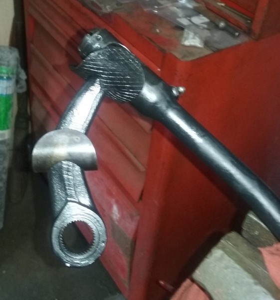
Using a bench grinder to grind about 1/16" off the faces of the pivot fork closest to the pedal allowed it to rotate slightly on the pivot, like the stock setup was designed to.![[IMG]](http://www.beamingpix.com/images/2017/09/11/9.20170202_131417_zpspmoma1ch.jpg)
I used a 1-29/32" long AN23-30A Clevis Bolt with a thin 10-32 nylon-insert lock nut as the pivot in place of a roll pin, and assembled everything using a little grease between the moving parts. The end of the bolt was then ground down to the surface of the nylon insert, and the assembly was painted.![[IMG]](http://www.beamingpix.com/images/2017/09/11/10.IMAG0081_zpsglxesbht.jpg)
![[IMG]](http://www.beamingpix.com/images/2017/09/11/11.IMAG0079_zpsciuyu0n4.jpg)
![[IMG]](http://www.beamingpix.com/images/2017/09/11/12.IMAG0073_zpszwzbocij.jpg)
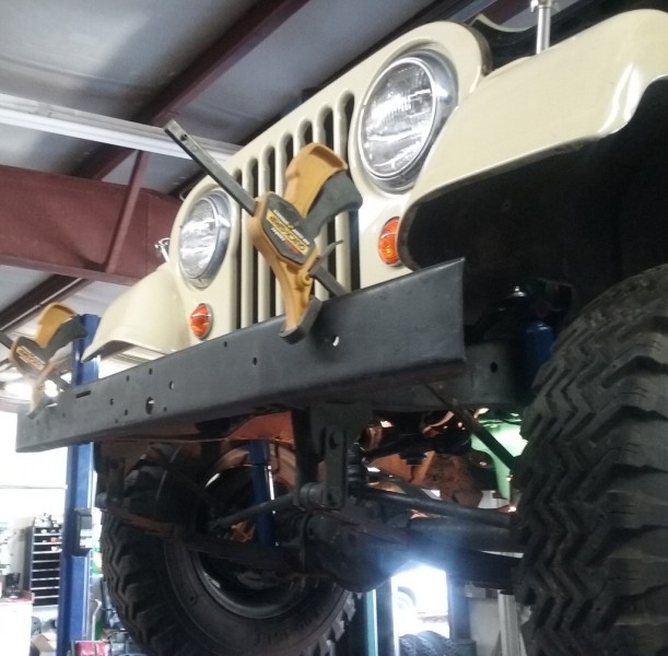
With these minor modifications, the Bronco pedal works great on the CJ. Speaking for myself, at least, it created a significant improvement in the jeep's overall driving comfort as compared to the stock gas pedal - and IMHO, it looks good at the same time.![[IMG]](http://www.beamingpix.com/images/2017/09/11/13.20170204_152737_zpsjulhthdx.jpg)
![[IMG]](http://www.beamingpix.com/images/2017/09/11/14.20170206_155957_zpsm7mf3cme.jpg)
Pedal depressed about halfway (note that most of my foot is resting on the floor):![[IMG]](http://www.beamingpix.com/images/2017/09/11/15.20170203_083003_zpsbsykpvxh.jpg)
Pedal "floored", fully depressed:![[IMG]](http://www.beamingpix.com/images/2017/09/11/16.20170203_084336_zpsnwxf1nws.jpg)
As a note of interest, this gas pedal is installed upside down from the way it was mounted by Ford on the Bronco. A buddy with a '76 Bronco told me that the mounting bracket on his gas pedal is closer to the bottom, rather than the top - so evidently the Broncos had a longer / lower accelerator control rod than the early CJs did.
In case anyone else wants to try this out, the Bronco gas pedal is Ford part number C5AZ-9735 D. When I was looking, there were many of these for sale on eBay, both used and NOS, and reproductions are available as well (though I'm not sure if or how well the repro pedals would work, as the one I used was a genuine Ford part).
Hope this is helpful to some others out there with a stock hanging gas pedal and a sore right shin!La -
The American Bosch WWF electric wiper motors first appeared on the Kaiser Jeep CJs during the mid-1960's (I believe sometime in '66), replacing the previous vacuum-operated wiper system. My 1967 CJ5 has the original WWF motors, which were still working except for the "parking" of the wiper blades that's supposed to occur when the switch is turned off. I know the jeep's original owner, and he did not recall the wiper motors ever having been serviced during their 50 year lifespan - so it seemed like a full rebuild might be a good idea.
![[IMG]](http://www.beamingpix.com/images/2017/09/11/1.20170106_114143_zpsfag4fxwv.jpg)
Instructions for installing and adjusting the WWF motors published by American Bosch in 1968:![[IMG]](http://www.beamingpix.com/images/2017/09/11/2.BoschWWFInstallationInstructionsPg1_zpsn9mikqaj.png)
![[IMG]](http://www.beamingpix.com/images/2017/09/11/3.BoschWWFInstallationInstructionsPg2_zpskzvivpcs.png)
![[IMG]](http://www.beamingpix.com/images/2017/09/11/3.BoschWWFInstallationInstructionsPg3_edited-1_zpszyqx0ihu.png)
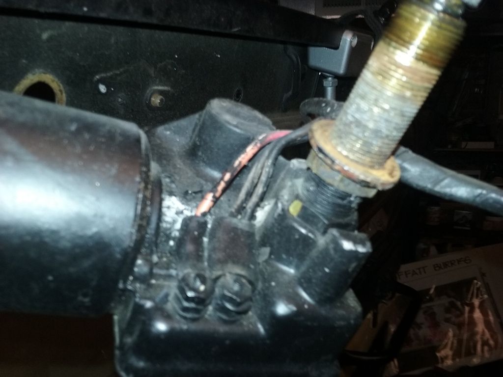
The factory-installed electric wiper motors on my '67 CJ5 are single-speed. The original one-speed wiper switch is a rather unusual four-terminal configuration. There are two separate "hot" red power wires leading from the switch to each of the two motors, as well as a constantly powered brown "park" wire, and the fourth bluish-white wire is the 12v input from the ignition switch. Some photos of the original switch are below (the first two were taken when I removed the switch, and the last two after it was cleaned):![[IMG]](http://www.beamingpix.com/images/2017/09/11/4.20161206_122234_zpshqgqyol2.jpg)
![[IMG]](http://www.beamingpix.com/images/2017/09/11/5.20161206_122111_zps6fpotjzt.jpg)
![[IMG]](http://www.beamingpix.com/images/2017/09/11/6.20161207_165943_zpsad5etl76.jpg)
![[IMG]](http://www.beamingpix.com/images/2017/09/11/7.20161207_170257_zpsdfxvwscw.jpg)
The wiring harness for my jeep, which was recently replaced, was built by Carl Walck at Walck's 4WD, who did a fantastic job with it. The one part of the harness that was non-standard, and was therefore not included with the main harness, was the windshield wiper wiring, which is a completely separate (and vehicle-specific) harness. I sent the old wiper harness, which was in pretty bad shape, to Carl and asked him to use it as a pattern to build a new one for me to the original specs, which he did. It turned out that was the first time he'd had a pattern in hand to build one from.
The only somewhat difficult part of removing and disassembling the motors was taking the wiper arms off of the splined heads on the wiper motor shafts. The problem is that there are very small metal clips in the ends of the wiper arms that have to be released in order to pull them off of the splines, but there is no angle from which these clips can be viewed when the wiper arms are installed - so I was working blind. After spraying a little PB Blaster into the splines to loosen them up some, I finally succeeded in removing them by using a small mirror and a hooked metal probe to press back the metal clips and slide the arms off of the splined heads.![[IMG]](http://www.beamingpix.com/images/2017/09/11/8.20170109_143748_zpsvnyjnolt.jpg)
![[IMG]](http://www.beamingpix.com/images/2017/09/11/9.20170109_143339_zpsfvtheymj.jpg) After unscrewing the 3/4" nut from the front of the threaded wiper shaft sleeve and unbolting the spacer at the other end of the motors, they could be pulled through the windshield and disconnected from the harness.
After unscrewing the 3/4" nut from the front of the threaded wiper shaft sleeve and unbolting the spacer at the other end of the motors, they could be pulled through the windshield and disconnected from the harness.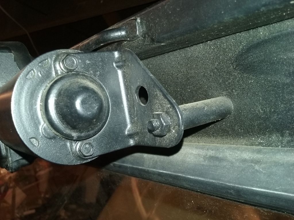
 There are four small screws that allow removal of the gearbox plate. I was pleased to find that even after 50 years of use, the gearboxes in both of the motors are in remarkably good shape. Note the circular brass "button" contact over the spring, which activates the motor's parking function.
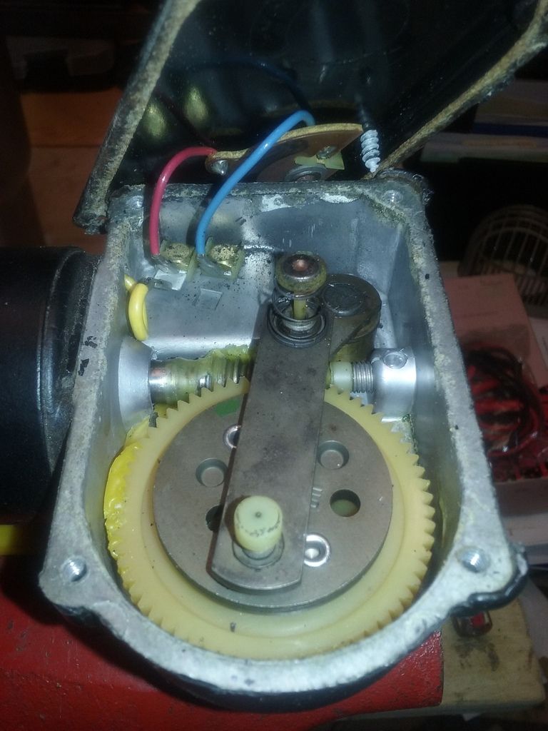 The parking circuit of these motors is an interesting design. Here's a link to an excellent post by Jon McKenzie on the Early CJ5 website, including photos, that shows how the wiring and the parking circuit work when operating as they're designed to:Though the gearboxes themselves were surprisingly clean when I disassembled them, the semicircular shaped electrical "bridges" that operate the motors' parking function were very dirty on on both motors, which is likely what caused them to stop parking at some point.
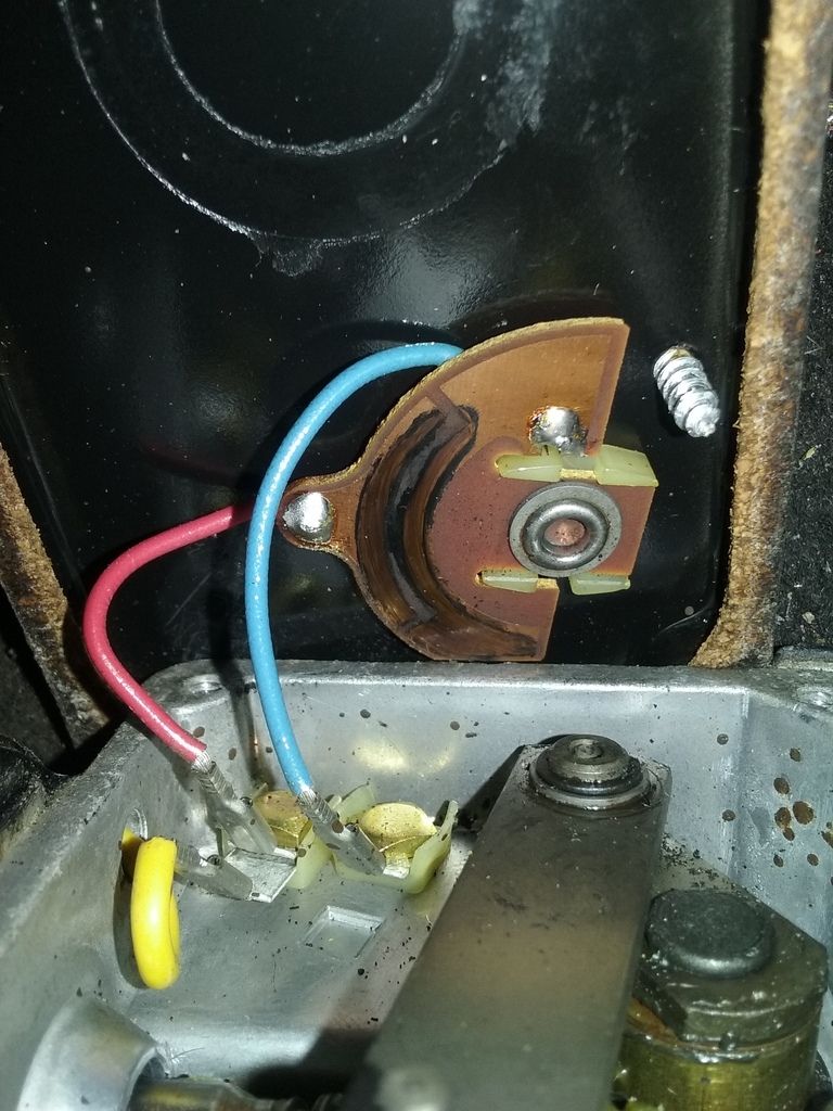 A small spring clip on the "crank" at the end of the wiper shaft retains the internal working parts. Once this is removed, the remaining internal parts can all be lifted out from the gearbox. Only the wiper shaft, which is swaged to the crank bracket on the housing end, and to the splined head on the other, is not removable from the housing.
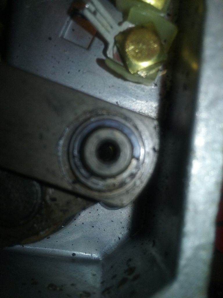 The wiper gearboxes were factory set for a 120-degree sweep:
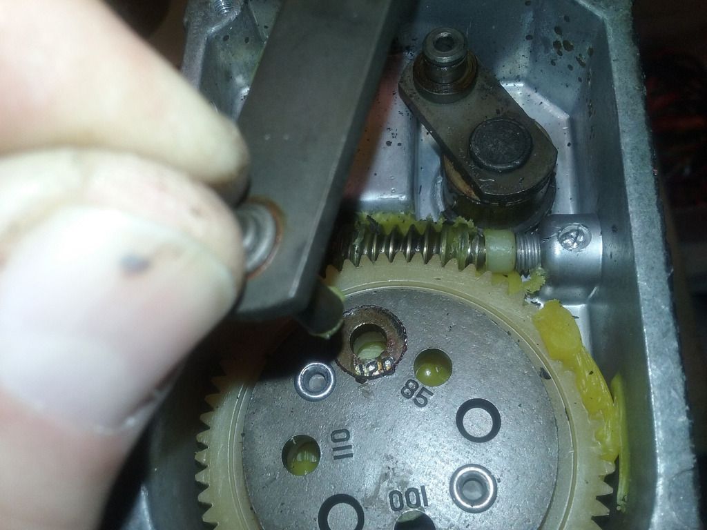
 After removing the two long machine screws that hold the parts of the motor together and attach it to the gearbox, disassembly of the motors was complete. The brushes and armatures of both motors are fortunately still in excellent shape, as are the bronze bushings, as there was no discernable runout / lateral end movement in either of the motor shafts.
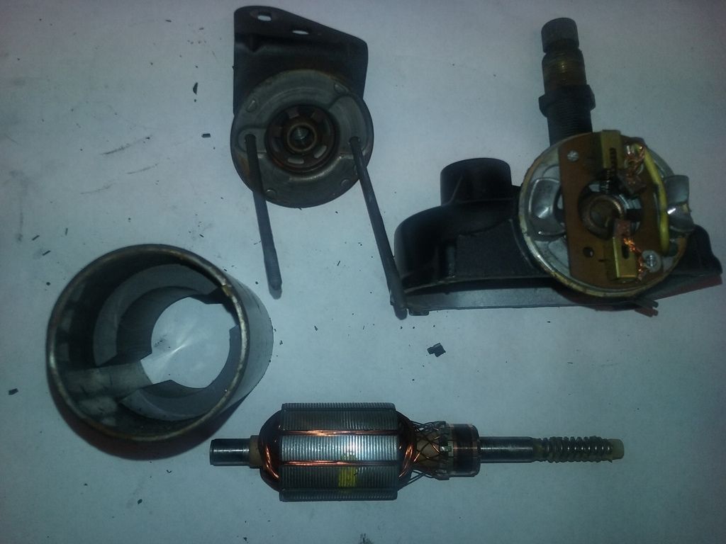 Some slight water intrusion had clearly occurred in the drivers side motor at some point, and I used a Dremel with a small circular wire brush to remove the rust inside the cylindrical motor casing and on the two ends. Note: If you have to do this, I would strongly suggest using a brass brush, rather than a steel one, on the Dremel. I learned the hard way that if a steel brush is used, the magnets inside the motor will collect ALL of the tiny wires that come off of the brush during use (and removing those wasn't fun!)
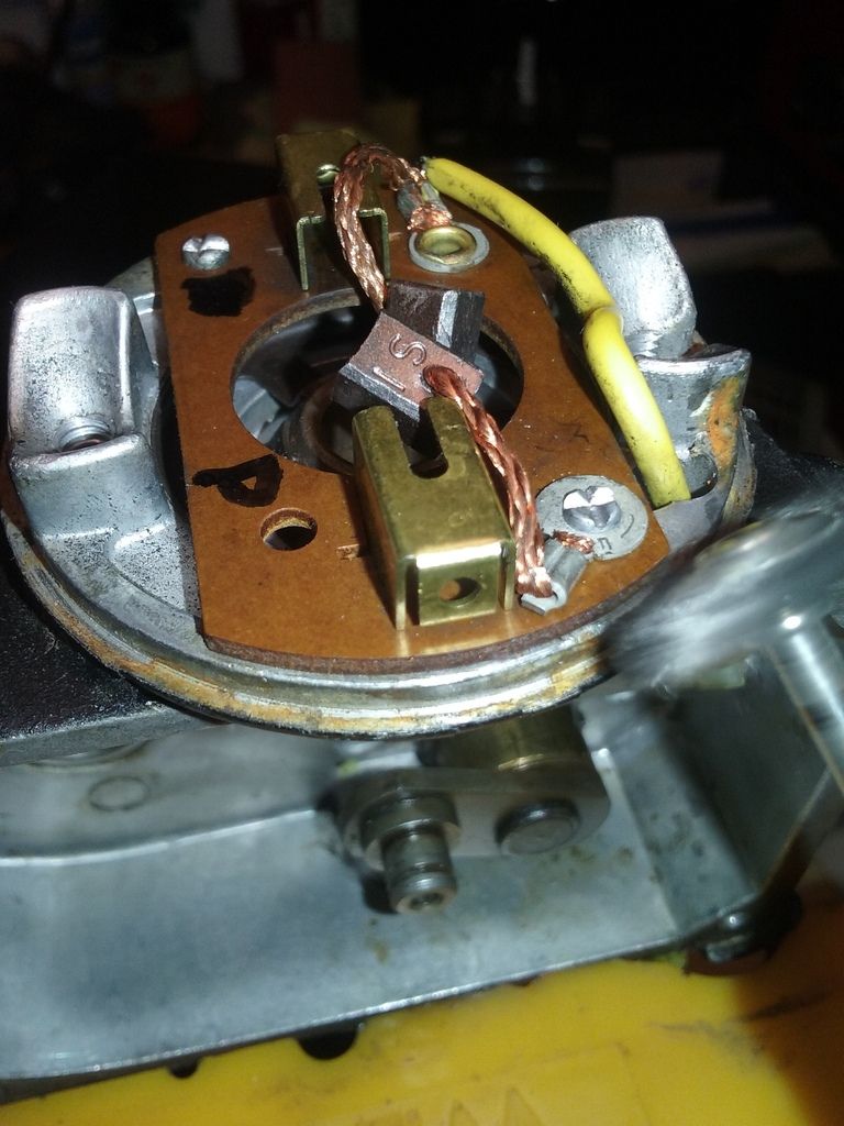 With the rust removed, and all parts thoroughly de-greased and cleaned with denatured alcohol, the motors are now ready for relubrication and re-assembly.I've been reading up a lot on greases - a subject about which I've always had a significant knowledge deficit - and have learned quite a bit. Among other things, what I've read is most often recommended for use in electric motors is polyurea-base grease of NGLI #2 consistency. Apparently this particular type of grease is extremely stable in terms of its viscosity over a wide temperature range, so it provides good bearing lubrication upon motor startup even in very cold or very hot conditions.Here's a grease of this type designed specifically for electric motor ball bearings: https://smile.amazon.com/gp/product/B017WKDTSA/ref=oh_aui_detailpage_o00_s00?ie=UTF8&psc=1 However, these particular motors have bronze bushings, not ball bearings, so I asked Moses about this offline. He felt this would be a good grease to use for this application as well, so I picked up a tube.Moses also recommended a particular Bosch Tool Gear Grease for the gearboxes , so I got a tube of that as well: https://smile.amazon.com/BOSCH-POWER-TOOLS-Replacement-Part-1615430005-Grease/dp/B002ENJ9OO/ref=sr_1_1?ie=UTF8&qid=1485183768&sr=8-1&keywords=bosch+tool+greaseThe problem of lubricating the rotating wiper shafts, as both of its end fittings are swaged and not meant to be disassembled, was solved by creating a simple "adapter" from a short piece of 5/8" ID x 7/8" OD tubing. This adapter allowed the connection of a grease gun to the end of the wiper shaft, and force (chassis) grease between the wiper shaft and the threaded sleeve. The tube was tightly hose-clamped to the end of the grease gun, using electrical tape to help make a grease-tight seal, and the other end placed over the spline end of the wiper shaft assembly and hose-clamped about halfway down the threaded brass sleeve (shown here without the hose clamps):
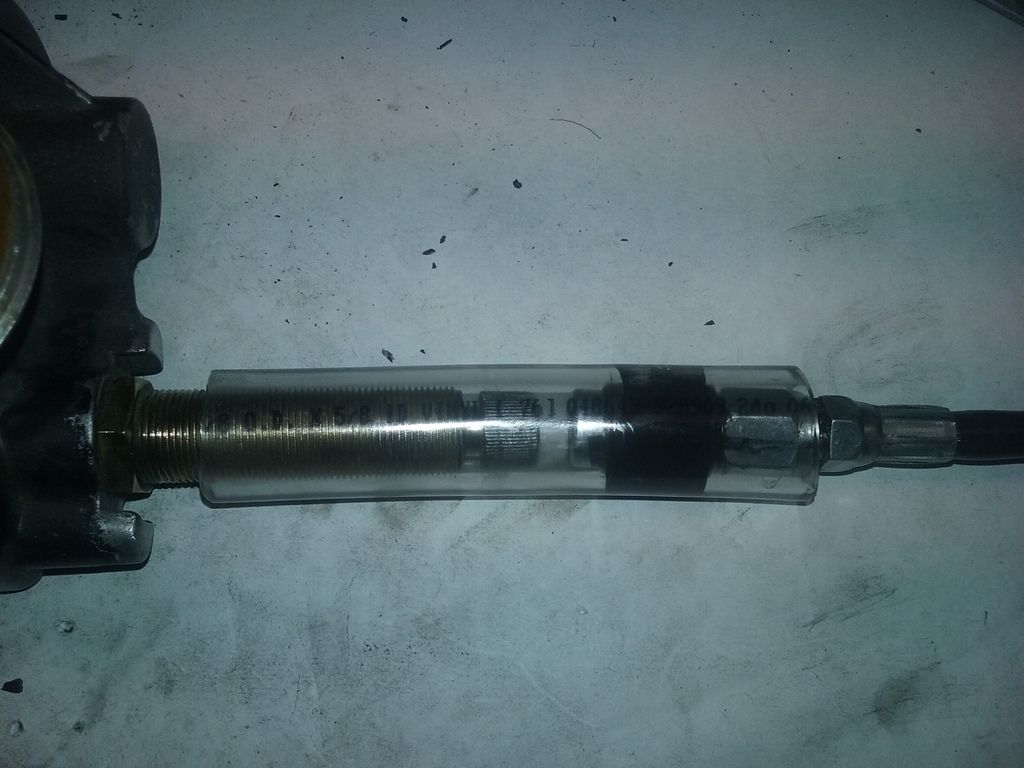 The amount of clearance between the shaft and sleeve is fairly tight - there is maybe 1mm of longitudinal shaft end play. It took a good deal of pressure and some time for the grease to make its way down through the tiny opening and start to ooze out of the other end of the sleeve / shaft assembly mounted in the housing. Working the small crank bracket on the wiper shaft back and forth to help distribute the grease evenly inside while pumping the gun's handle, the grease eventually made it all the way through (though I had to stop applying pressure when the tube expanded so much that I was afraid it might actually burst):
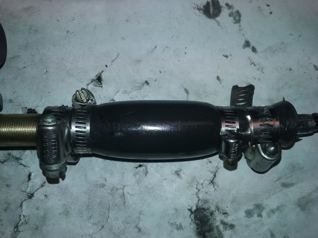 After unscrewing the 3/4" nut from the front of the threaded wiper shaft sleeve and unbolting the spacer at the other end of the motors, they could be pulled through the windshield and disconnected from the harness.
![[IMG]](http://www.beamingpix.com/images/2017/09/11/10.20170107_124112_zpsjy8zp1pj.jpg)
![[IMG]](http://www.beamingpix.com/images/2017/09/11/11.20170106_165926_zps5gbt4hf2.jpg)
There are four small screws that allow removal of the gearbox plate. I was pleased to find that even after 50 years of use, the gearboxes in both of the motors are in remarkably good shape. Note the circular brass "button" contact over the spring, which activates the motor's parking function.![[IMG]](http://www.beamingpix.com/images/2017/09/11/12.20170117_151028_zpsrrvpiown.jpg)
The parking circuit of these motors is an interesting design. Here's a link to an excellent post on this forum by jwmckenzie (Jon McKenzie) including photos that show the original wiring arrangement and how the parking circuits work when operating as they're designed to:
Wiper motor question?
Though the gearboxes themselves were surprisingly clean when I disassembled them, the semicircular shaped electrical "bridges" that operate the motors' parking function were very dirty on on both motors, which is likely what caused them to stop parking at some point.![[IMG]](http://www.beamingpix.com/images/2017/09/11/13.20170113_171422_zpshmv29p29.jpg)
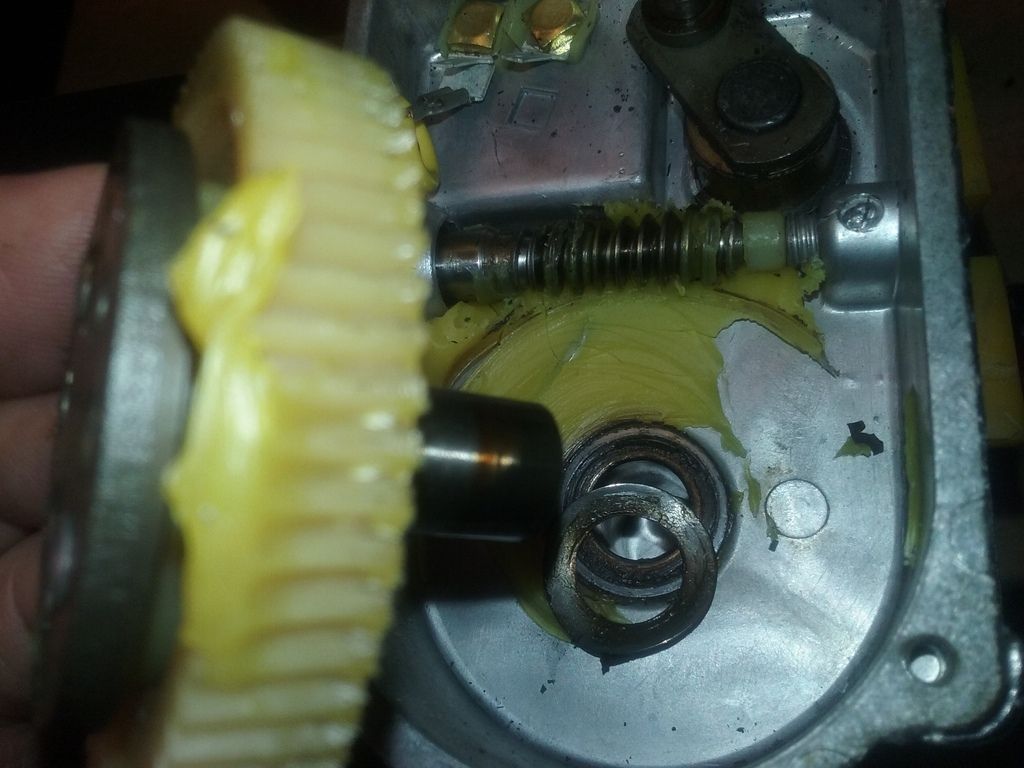
A small spring clip on the "crank" at the end of the wiper shaft retains the internal working parts. Once this is removed, the remaining internal parts can all be lifted out from the gearbox. Only the wiper shaft, which is swaged to the crank bracket on the housing end, and to the splined head on the other, is not removable from the housing.![[IMG]](http://www.beamingpix.com/images/2017/09/11/14.20170117_151853_zps1n1hypen.jpg)
The wiper gearboxes were factory set for a 120-degree sweep:![[IMG]](http://www.beamingpix.com/images/2017/09/11/15.20170117_152208rev_zpshgxlxa71.jpg)
![[IMG]](http://www.beamingpix.com/images/2017/09/11/16.20170117_152311_zpsfnb1rvam.jpg)
After removing the two long machine screws that hold the parts of the motor together and attach it to the gearbox, disassembly of the motors was complete. The brushes and armatures of both motors are fortunately still in excellent shape, as are the bronze bushings, as there was no discernable runout / lateral end movement in either of the motor shafts.![[IMG]](http://www.beamingpix.com/images/2017/09/11/17.20170117_162741_zpsvrqywtby.jpg)
Some slight water intrusion had clearly occurred in the drivers side motor at some point, and I used a Dremel with a small circular wire brush to remove the rust inside the cylindrical motor casing and on the two ends. Note: If you have to do this, I would strongly suggest using a brass brush, rather than a steel one, on the Dremel. I learned the hard way that if a steel brush is used, the magnets inside the motor will collect ALL of the tiny wires that come off of the brush during use (and removing those wasn't fun!)![[IMG]](http://www.beamingpix.com/images/2017/09/11/18.20170123_091936_zpspki6epty.jpg)
With the rust removed, and all parts thoroughly de-greased and cleaned with denatured alcohol, the motors are now ready for relubrication and re-assembly.
I've been reading up a lot on greases - a subject about which I've always had a significant knowledge deficit - and have learned quite a bit. Among other things, what I've read is most often recommended for use in electric motors is polyurea-base grease of NGLI #2 consistency. Apparently this particular type of grease is extremely stable in terms of its viscosity over a wide temperature range, so it provides good bearing lubrication upon motor startup even in very cold or very hot conditions.
I came across a grease of this type online designed specifically for electric motor ball bearings: Amazon.com: Mobil Polyrex EM Electric Motor Bearing Grease, Blue, 13.7 oz. Tube: Automotive However, these particular motors have bronze bushings, not ball bearings, so I asked Moses Ludel at the 4WD Mechanix site about this. He felt this would be a good grease to use for this application as well, so I picked up a tube. Moses also recommended a particular Bosch Tool Gear Grease for the gearboxes , so I got a tube of that as well: Amazon.com: BOSCH POWER TOOLS Replacement Part 1615430005 Grease: Home Improvement
The problem of lubricating the rotating wiper shafts, as both of its end fittings are swaged and not meant to be disassembled, was solved by creating a simple "adapter" from a short piece of 5/8" ID x 7/8" OD tubing. This adapter allowed the connection of a grease gun to the end of the wiper shaft, and force (chassis) grease between the wiper shaft and the threaded sleeve. The tube was tightly hose-clamped to the end of the grease gun, using electrical tape to help make a grease-tight seal, and the other end placed over the spline end of the wiper shaft assembly and hose-clamped about halfway down the threaded brass sleeve (shown here without the hose clamps):![[IMG]](http://www.beamingpix.com/images/2017/09/11/19.20170119_140114_zpsbigipxrt.jpg)
The amount of clearance between the shaft and sleeve is fairly tight - there is maybe 1mm of longitudinal shaft end play. It took a good deal of pressure and some time for the grease to make its way down through the tiny opening and start to ooze out of the other end of the sleeve / shaft assembly mounted in the housing. Working the small crank bracket on the wiper shaft back and forth to help distribute the grease evenly inside while pumping the gun's handle, the grease eventually made it all the way through (though I had to stop applying pressure when the tube expanded so much that I was afraid it might actually burst):![[IMG]](http://www.beamingpix.com/images/2017/09/11/20.20170120_135352-r_zpsjg5y5hi4.jpg)
![[IMG]](http://www.beamingpix.com/images/2017/09/11/21.20170120_081745_zpsyj5vkb3m.jpg)
As a sealant for reassembly, I ordered a tube of Loctite Superflex sealant (https://www.amazon.com/SEPTLS44259330-Superflex-Silicone-Adhesive-Sealants/dp/B001VXWCTM), which Moses mentioned that he has successfully used in some recent axle builds. He described it as a sealant that remains pliant, and may seal better than the more common RTVs for this type of application. Be aware however that it “cannot be painted” when detailing.
This is where I am with the rebuild at present, waiting for the Loctite Superflex to arrive.I'm wondering if I should seal not only the gearbox lid with the Loctite, but also the motor housings - though I can see no evidence that these were sealed originally. Would there be any problem with using the Loctite to also seal the joints around the ends of the motors, or would they be better off left unsealed as originally manufactured? -
Hi Monty,
Very nice jeep! It reminds me a lot of my '67 CJ5 when I bought it 7 years ago.
Walck's 4WD built the wiring harness for mine, and I can honestly say that it is superb in every way. It is also probably as close to the original wiring harness in appearance as could be re-created today, though the quality of the materials exceeds the original factory specifications and electrical requirements. The ends are soldered, and the wire lengths are pre-determined, which helps to minimize the work necessary to install the harness. It not only fit well, but came with the proper connectors, bulb sockets, etc.
Carl Walck builds these harnesses himself, and is available by phone to answer any questions that may arise during installation. Since he builds each one individually, Carl is able to customize them as necessary. He also sends a questionnaire to fill out before he builds it, in order to make sure he correctly accommodates for various production changes that were made within model years (for example, back-up lights were added during the mid-1967 model year). Here's a link to Walck's website's page on wiring harnesses: http://walcks4wd.com/walcks-willyswiringharnesses/
I would highly recommend Walck's, not only for wiring harnesses, but for most any other Jeep parts you may need. Carl and his family are, as the saying goes, "Good People".
I also agree 100% with 60Bubba's comment re. Moses' book....you've given an ideal gift to your new mistress!

Maury
-
Part 2: Rebuilding An Original Ignition Switch
The first thread in this series, Vintage Jeep Ignition Switch - Part 1: Refreshing An Original Switch , covered the internal cleaning of an original switch without disassembling it. That process may suffice in some cases to restore an older switch to good working order. In the case of the original 50-year old ignition switch from my 1967 CJ5, however, it proved to be insufficient to fully fix the problem. This thread picks up where I left off in Part 1.
When Moses and I initially discussed this idea in an off-forum conversation (much of which is excerpted in When to Restore a Vintage Jeep Ignition Switch), he and I both expressed some apprehension about the wisdom and viability of de-crimping and then re-crimping a 50-year-old diecast metal switch housing in order to repair or replace the switch's internal parts. My original inclination to get the switch working was to try to clean it without taking it apart, as discussed in Part 1. However, when that process failed to fully fix the intermittent connectivity issue on the Accessory terminal, rebuilding it seemed the only option left to try if I wanted to continue to use it (which I do, particularly since I still have one of its original Jeep logo keys).
The OEM ignition switch for my CJ5 (Kaiser Jeep part # 924918), which was manufactured by Pollak, is unfortunately no longer available. As far as I've been able to discover, there were no crossover uses of that particular switch with any other vehicles.
However, in researching this subject on the internet, I realized that certain other similar ignition switches made by Pollak (or Aetna-Pollak, as it was called in the late '50's and early '60's) during the same general time frame might very well share their internal parts with my original switch. If so, having an NOS example of one of those switches would allow me to cannibalize its parts to repair mine - assuming that I could successfully disassemble and then reassemble mine without ruining the diecast housing.
The switch that seemed to be the closest visual match to my Jeep's original ignition switch was a 1956-63 Rambler / Nash switch (AMC part # 3158414) made by Aetna-Pollak. It was almost certainly produced a few years before the Pollak switch in my jeep was manufactured, and had a much shorter lock cylinder socket. However, the "business end" of the switch containing the internal parts appeared to be outwardly identical to that of my CJ5's OEM switch.
NOS Rambler / Nash ignition Switch (L) and OEM Jeep CJ5 Ignition Switch (R):

To test this theory, I bought an NOS Aetna-Pollak manufactured Rambler / Nash 3158414 ignition switch on eBay. Also listed were several 3158414 replacement switches made by another manufacturer (Sorensen, whose products were carried under several different brand names), but the OEM Aetna-Pollak version I was looking for was likewise available.
Here's a photo of a nice NOS example of this switch:

When the NOS switch I ordered arrived, it became clear that my original ignition switch was indeed nearly identical to the Rambler / Nash switch, with the exception of the length of the lock cylinder socket and the configuration of the 1" threaded portion that extends through the dashboard. The two switches shared the same base, and it seemed very probable that their internal operating parts would likewise match.

As can be seen above, the thermoplastic / bakelite base is secured into the diecast housing by six crimps around its circumference. I decided it would be a good idea to disassemble the "donor" switch first before trying to take my original switch apart, as this would give me some practice with de-crimping an older diecast metal switch housing.
I set about taking the NOS Rambler / Nash switch apart by first placing its lock cylinder socket in a vise with "soft jaws" type inserts. Note: I would highly recommend these polyurethane vise inserts to anyone planning to rebuild a similar ignition switch, as I found them to be an indispensable tool in this project:
https://smile.amazon.com/gp/product/B00004XPVT/ref=ox_sc_sfl_title_1?ie=UTF8&psc=1&smid=ATVPDKIKX0DER
To de-crimp the housing from the base, I used used a small 1/8" flat screwdriver, gently twisting it back and forth between the crimps and the plastic base, to very gradually and slowly work each crimp outward.

I turned the switch housing as I worked. Soon, there was enough space between the metal and the plastic base to move up to a 1/4" flat screwdriver. It took about 15 or 20 minutes of patient, careful work to bend all six crimps far enough outward to remove the plastic base from the housing.
Once it was apart, it was easy to see how the switch operates. It's extremely simple, and in fact, there is only one moving assembly inside it. This assembly includes a plastic core keyed to a copper alloy disc with a coil spring in between them that presses the disc into the terminal contacts in the base. The assembly turns with the lock cylinder to make the proper connections to the stud terminals on the base at each different ignition key position. Also, the copper disc has a starter tab that contacts another tab on the base when the key is turned to the start position, causing that circuit to close (and the starter motor to engage).
The NOS switch with the base removed, showing the copper alloy disc:

The rotating assembly (center) lifted out and turned over:

By this time I was both practiced and "on a roll" - so I moved on to disassembling my original switch using the same technique, doing as little damage to the metal as I could as the crimps were worked outwards. It's not difficult to take these switches apart, though it's a bit painstaking to do so while keeping the diecast housing in re-usable condition at the same time.
Once it was apart, two things immediately became apparent. First, the internal parts were definitely a good match for those in the NOS Rambler switch. Second, the reason my original switch had been having a connectivity problem was clear. Even after its cleaning with Deoxit (see Part 1 of this series), the rotating copper disc showed evidence of burning in several areas. Also, the starter tabs on both the disc and the base were significantly burned:

The only noticeable difference between the old internal switch parts and the NOS parts was that there were two copper tabs on either side of the NOS copper disc that snapped into tapered grooves in the edges of the plastic core. These tabs keep the coil spring slightly compressed and the rotating assembly parts from separating. The slightly later OEM Jeep switch did not have these two tabs for some reason, but having them on the NOS part made reassembly easier.

I cleaned the original housing with denatured alcohol to remove the remaining original grease that the Deoxit hadn't dissolved, and cleaned the NOS parts removed from the Rambler / Nash switch the same way. After letting the alcohol evaporate, I coated the NOS copper alloy disc and the terminal contacts in the base with Deoxit Shield, which is designed to protect and lubricate clean electrical contacts in potentially harsh environments. I let this dry completely before continuing with the reassembly.

At Moses' suggestion, I contacted Pollak, which is still in business, to ask what type of grease they use in their current switches (which incidentally are remarkably similar to the ones they made 50+ years ago). Their rep indicated that they now use a grease called Rheolube 363. Although Rheolube 363 is unavailable in the retail market, I was able to find its properties online. After sharing that info with Moses, he recommended using a lithium-based grease he has found to be very effective, UltraLube LMX, for use in the rebuilt ignition switch. Here's a link to that product (though it is available locally in many areas):
Using UltraLube LMX, I thoroughly greased the inside of the cleaned original housing, and then started reassembly of the switch.
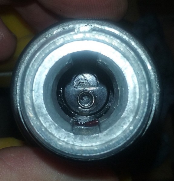
As the switch was being reassembled, I made sure to align the rotating assembly so that the semicircular hole near the center of the disc - into which semicircular tab at the end of the the lock cylinder fits - was correctly positioned toward the top of the switch (where the small groove is cut into the threaded end of the lock cylinder socket). The photo below, looking down the lock cylinder socket, shows the proper positioning of the rotating assembly:
Additionally, the plastic base has a rectangular notch which must be aligned with a small tang on the metal housing. The base also has six evenly spaced indentations around its edge, which correspond to the locations of the six crimps in the diecast metal housing. The notch and the indentations in the plastic base, as well as the tang in the housing (the rectangular "bump" with grease on it), are visible in this photo:

After aligning the notch in the NOS base with the corresponding tang in the housing, the base could be installed. It was a little tricky to get the new base fully seated, but using the vise (with only extremely light pressure) ensured that it was pressed all the way in:

After lightly clamping the lock cylinder socket of the switch housing between the soft jaws of the vise, while continually pressing down on the base with my fingers, I used the edge/side of the end of a round steel punch, tapping it with a hammer very gently to gradually recreate the concave shapes of the original six crimps in the diecast housing:


Tapping each re-crimp into the housing a little a time, I made multiple passes over each one, rather than trying to form any of them in a single pass. Also, each time I moved to another crimp, rather than working in a circular motion to the next adjacent one, I went to the crimp 180 degrees across the base. From there, I then rotated to the adjacent crimp, went to the one 180 degrees across the base from that point, and so on.
I worked around the switch this way, making at least four complete rotations and turning the housing between the soft jaws of the vise as I went. This process ended up re-crimping the original metal housing around the NOS plastic base surprisingly well. The base is very tightly secured, with no detectable movement between it and the housing.

Moses pointed out that if someone rebuilding a similar ignition switch was concerned about the possibility of moisture intrusion through the joint between the housing and the base, one way to mitigate this would be to fill the groove along that joint with a 2-part plastic epoxy. He cautioned though that epoxy is not strong enough to substitute for crimps.
The lock cylinder, having already been cleaned and lubed in Part 1 of this series, was reinstalled in the housing, using a small knife to depress the retainer clip and allow the cylinder to slide in:

Turning the key through its positions, I checked the rebuilt switch for continuity, and am glad to report that it performs perfectly. Testing for resistance, the ohmmeter registers much less than 0.5 ohms across each of the closed contacts, indicating good connections. When the key is turned, it now "feels" like a brand new ignition switch.
After shining up the housing, bezel nut, and terminal studs a bit, the rebuild was complete, and the switch was ready to be returned to service.
OEM ignition switch as shown in the 1966 Universal Jeep Parts List, and the newly rebuilt OEM ignition switch:

-
Part 1: Refreshing An Original Ignition Switch
Image of OEM Jeep CJ5 ignition switch from the 1966 Universal Jeep Parts List:

As noted in the initial thread Moses started based on our off-forum conversations around this issue (When to Restore a Vintage Jeep Ignition Switch), I've recently been experiencing a problem with my 1967 CJ5's original Pollak ignition switch, which is now 50 years old. Specifically, the switch would sometimes fail to connect on the Accessory (ACC) terminal when in the Ignition "On" position. The Jeep would start and run normally, but the radio, windshield wipers, and other electrical devices connected to the Accessory terminal would occasionally fail to operate when the engine was running.
The discovery of this problem led me to wonder if the switch could either be 1) Refreshed, i.e. cleaned internally without actually disassembling it; or if not, 2) Disassembled and rebuilt. This thread will cover the first of these potential options.
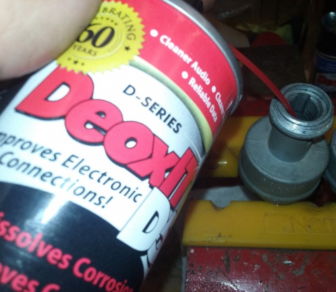
As noted in the previous thread, as I was exploring various ideas, I was referred by someone I contacted online to Scott Versaw, who is an expert restorer of vintage automotive electrical items. Scott was extremely kind and offered lots of great advice, including the possibility of trying a product line called Deoxit, which he referred to as the "secret sauce" he has used successfully in the past for cleaning closed switches.
I decided to try that option first, so I bought a spray can of Deoxit D Series cleaner, as well as one of Deoxit S5S Shield (see previous thread for links to these products). To recap from that thread, Deoxit cleaner is basically a specialized solvent designed to remove corrosion and other contaminants from switch contacts, and Deoxit Shield is designed to be used after the cleaner to protect and lubricate the contacts. The reviews of both indicate that they are excellent products that are used for many types of electric and electronic device cleaning, including among others ignition switches on motorcycles, aircraft, and many types of equipment.
To begin the cleaning process, after disconnecting the battery and removing the ignition switch bezel nut from the front of the dash, I disconnected the switch from the wiring harness by removing the wires from one terminal at a time. I used twist-ties through the wires' ring terminals in order to keep the wires on each contact together, and wrote on masking tape wrapped around each bundle of wires - again, one terminal at a time - to indicate which terminal (ACC,IGN,BAT, or ST) they were removed from so that I wouldn't mix any of them up during reassembly.
Here's a photo of the base of the ignition switch before it or any of the wires were removed:

The still-connected switch pulled out from behind the dash (with the bezel nut screwed back on temporarily):

After clearly marking each set of bundled wires and disconnecting the switch, I removed the lock cylinder from the switch housing. In this particular switch, this is done by rotating the key to the "on" position and using a thin, straight metal tool (like a 1/16" Allen wrench) to press the spring-loaded retainer clip on the lock cylinder through the small hole in the "neck", or lock cylinder socket. Once this small brass clip (visible below in the center of the lock cylinder) is depressed slightly toward the center of the lock cylinder, the cylinder can easily be pulled out of the housing.
The photo below shows the lock cylinder upon its initial removal from the switch. I'm fortunate to have one of the original Jeep logo keys that came with the vehicle when it was new, so I thought I'd digitally immortalize it here:
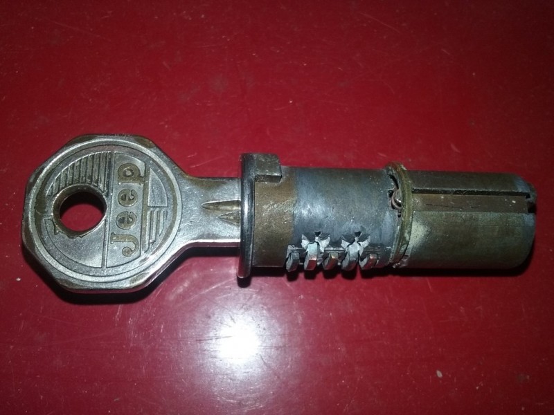
I first cleaned and lubricated the lock cylinder as shown below.
For those unfamiliar with how this type of lock works, as the key is inserted, it moves through five hollow, spring-loaded brass wafers in the cylinder. These wafers move according to the height (or cut) of the inserted key at each wafer's particular location within the cylinder.
As it is inserted into the lock, the correct key will move the five wafers so that all of their edges are flush with the outside of the cylinder, allowing it to rotate inside its socket in the switch housing (and turn the ignition switch). In the "Off" position, as the key is removed from the lock, tiny internal springs move these brass wafers slightly outward to extend below the bottom of the cylinder. The edges of the extended wafers slide into a longitudinal slot in the lock cylinder's socket in the switch housing, which prevents the cylinder from being turned. The photos below illustrate this:
1. Lock cylinder with key in; 2. Lock cylinder with key out; 3. Lock cylinder socket showing wafer slots

Over the life of the vehicle, the key being pushed into and pulled out of the lock thousands of times causes wear on both the key and on these brass wafers, resulting in tiny metallic particles gradually building up in the lock cylinder and in the switch. I suspect that this lock cylinder had probably never been removed during its 50 years in service, as quite a bit of this metallic "dust" had collected inside it.
To remove this metallic particle dust, I put the lock cylinder in a small container (a clean plastic film canister) of denatured alcohol and moved the key in and out of the keyway over and over again until the metal particles stopped coming out of the cylinder. Note that the dust removed from the lock cylinder is entirely inside the container (and is not the metal filings you see scattered on the work bench in the photo below):

The inside of the container after the lock cylinder cleaning, showing the metallic particles that came out of the cylinder:

There was some minor corrosion on the cylinder that needed to be cleaned off, which the denatured alcohol and a wire brush easily removed. I let the denatured alcohol evaporate, and helped this along by using a can of compressed air (the type used for electronics cleaning) to blow out of the inside of the keyway thoroughly. Once the lock cylinder was completely dry inside and out, I used an excellent lock lube I keep on hand called Houdini to lubricate the cylinder and wafers ( https://smile.amazon.com/HOUD1-Houdini-Lock-Lube/dp/B00C5JFKKE/ref=sr_1_1?s=hi&ie=UTF8&qid=1483310069&sr=1-1&keywords=houdini+lock+lube ). The cleaned, lubed cylinder was then ready to reinstall in the switch once it had likewise been cleaned.
One challenge with trying to clean this particular type of ignition switch is that without disassembling it, there are no openings through which to apply a cleaner to the internal parts except the open lock cylinder socket. Accordingly, I sprayed Deoxit cleaner through this opening, then put the lock cylinder back in so that I could move the key back and forth to hopefully work the cleaner into and through the internal parts of the switch. I repeated this several times, and eventually, dirty (gray) cleaner fluid leaked out between the plastic terminal base and the diecast metal housing.
I kept repeating the process until the cleaner fluid that was leaking out became clear. Note the white paper towel placed just below the switch, which I changed out with each spray-and-rotate cycle in order to assess the color of the cleaner fluid that was leaking out each time. (Note also that you can barely see the edge of the small hole through which the lock cylinder retainer clip is released just below the threaded neck toward the right side):
The instructions indicate that the Deoxit D5 cleaner needs to evaporate completely before the application of Deoxit Shield. Since the switch was closed, I figured the evaporation process would likely occur very slowly. In order to hopefully accelerate this, I hung the switch upside down suspended with twist-ties in front of a warm air supply vent for several days to allow it to drain and/or evaporate thoroughly:

After letting the cleaned switch dry for several days, I applied Deoxit Shield in the same way I'd used the cleaner previously. After spraying it into the lock for a few seconds, I reinstalled the lock cylinder and rotated it back and forth with the key to work the sprayed liquid into the internal switch parts.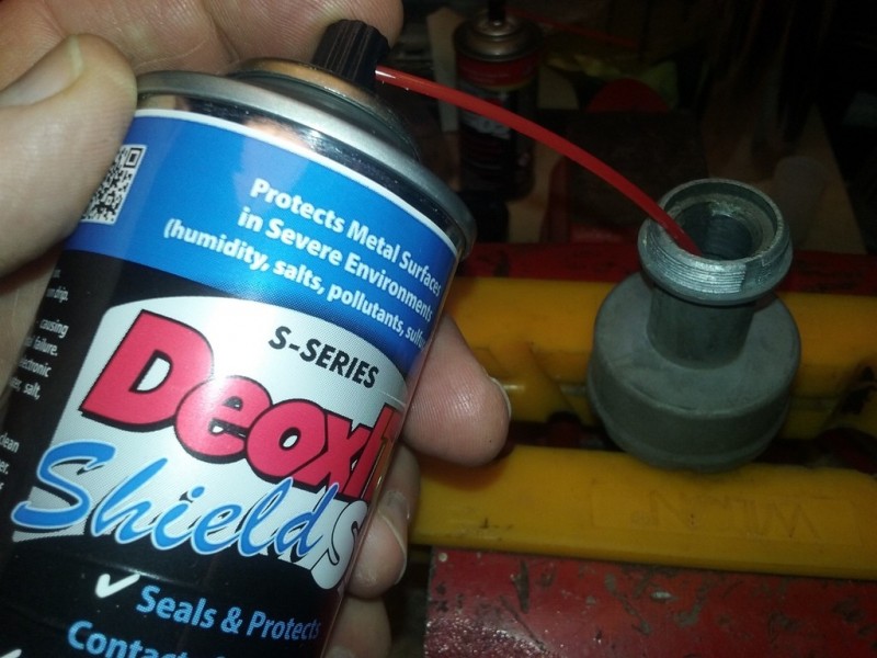
After the Deoxit Shield had dried, I tested the electrical continuity of the switch. The initial problem with the switch had been an intermittent connection between the ACC terminal and the IGN terminal. Using a continuity tester, I rotated the switch through its various positions, checking this connection probably 40 times.
And....drum roll, please....
It failed.
Though the intermittent connection / resistance problem at the Accessory terminal was definitely better after cleaning than it had been beforehand, the problem did not vanish entirely. Twice during this testing, the ACC terminal failed to connect with the IGN terminal as it should have. This represented about a 60% reduction in the failure rate experienced before the switch was cleaned.
Had the switch been in better shape internally, I suspect the Deoxit products may very well have done the job. However, the degree of wear, corrosion, and/or burned contacts present in the original switch after 50 years of use was evidently too great for the "Deoxit Process" to succeed completely (though it did help).
Rather than reinstall a switch that clearly still has a problem, I decided to try rebuilding it altogether, which I will cover in another thread ( Vintage Jeep Ignition Switch - Part 2: Rebuilding An Original Switch ).
-
Moses,
As you know, the Rheolube 363 has a lithium base, and the Nye website describes it is as:
"Rust inhibited. A lithium soap thickened, light viscosity, synthetic hydrocarbon grease intended for bearings, sliding surfaces, gear trains, and switchgear. Excellent for wide temperature performance."
.....but do you think this Dupont Teflon grease, the description for which ( http://www.performancelubricantsusa.com/product/severe-service-grease.php ) states:
"Overbased Calcium Sulfonate thickener offers water washout and mechanical stability properties which far surpass lithium complex greases......(applications include) bearings, bushings and gear couplings, etc .... -40°F (-40°C) to 350°F (177°C)..... can be used as an upgrade or replacement for most general purpose greases"
would suffice instead?
-
Here's Fred's photo of the rear of his current bracket showing the pinch bolt and compression slit.
He will need to check the torque on that nut and the top shaft nut, but assuming they are both are tightened to spec....given the current wobble at the bottom end of the bellcrank shaft....could there be any other cause for that wobble besides wear on the shaft, and/or in the cylindrical shaft receptacle inside the bracket?
Incidentally, the bracket on my 1967 CJ5, which was built in August 1966, a few months before Fred's jeep, has the same 7/8" dia. shaft bracket (though mine still has the riveted original).

-
I had a conversation with Fred last night, and asked him to check the pinch bolt to ensure that it is there and that it's tightened to the proper torque. I'll ask him to take a photo of his bracket showing that bolt, and the compression slit that should be there as well.
In addition, before he orders the takeoff bracket, assuming he decides to do that, he should as you suggest confirm that it has a compression slit.
-
I think I found the bellcrank bracket used on Fred's jeep, which appears to be a 7/8" shaft bracket that's listed as a takeoff part at Willys Jeep Parts (number 807009 https://www.willysjeepparts.com/Bell_Cranks_B.htm - photo below). Fred's going to take a close look at his bracket this weekend to verify whether or not it is in fact the same one.
If it is the same part, given that he'll have to transport his CJ5 a good ways to get it worked on by a mechanic he found who has experience with older jeeps, I'm going to encourage Fred to go ahead and buy one of these brackets (after verifying with the seller that as a takeoff part, it is in good, usable condition), along with a new 7/8" shaft kit, including all new bearings, etc. (like http://walcks4wd.com/bell-crank-kit-78-2a-3a-3b-cj5.html ). Fred already has an NOS bellcrank that was just installed a few months ago.
This way, along with a printout of the .pdfs from the manual that you were kind enough to provide, the mechanic will have all the information and major parts in hand he might possibly need to rebuild the bellcrank assembly, and hopefully solve the problem.
Will let you know the outcome of this situation.
Thank you so much for the benefit of your jeep wisdom, Moses!

-
I was evidently not completely clear in my initial post - sorry for any confusion I may have created:
The bellcrank does not appear to be wobbling on the shaft, so I don't think the bearings are the issue in this case. The problem is that shaft itself, for some reason, is moving somewhat inside the support bracket . This movement can be seen at the end of the shaft when the steering wheel is turned back and forth.
I suspect this movement of the shaft in the bracket may be what is causing the steering wheel not to return to center following a turn as easily as it should. When the end of the shaft moves side to side slightly while the bracket remains stable, that movement in turn creates pressure / friction on the spacer washer above the bellcrank - which I think may be the reason the steering wheel needs a bit of "help" to return to center after a turn to the left or right.
Does that make more sense?
-
This past weekend I visited my brother-in-law, Fred, who owns a 1967 V6 CJ5. This is the first time I'd done so since rebuilding the original Ross steering gear for his jeep earlier this year, and I was very much looking forward to driving it.
When I did so, I noticed that while the steering wheel had significantly less play than it did before the gear rebuild, it was definitely not as great of an improvement as I'd expected to see (i.e. quite a bit less of an improvement than I'd experienced after rebuilding the box for my own V6 CJ5). After his rebuilt box was installed, the play at the edge of the steering wheel was cut approximately in half from what it had been - from about 5" to 2-1/2" or so. When driving it, I also noticed that the steering wheel did not return to center following a turn on its own without a little "help" from the driver.
We took turns looking at the steering linkages while one of us turned the wheel back and forth within the free play area to try to determine where the "slack" was. It quickly became clear that the bottom end of the steering bellcrank shaft, which had been recently worked on by a friend of Fred's who also installed the rebuilt steering gear for him, moves side to side about 3/32 of an inch or so when the steering wheel is being turned back and forth. (This struck me as potentially dangerous, as if that shaft were to fall out while the jeep were being driven, the steering would immediately be lost altogether.)
The bellcrank shaft bracket is stable / stationary while this sideways movement at the lower end of the shaft is occurring. This bracket was replaced by a previous owner at one time, as it is bolted, rather than riveted, to the frame.
To further complicate the question, we are not sure if his jeep would originally have had the 7/8" diameter bellcrank shaft, or the larger 1-1/8" shaft. This change was made sometime during the 1967 model year on the V6 CJ5s. The serial number indicates that my '67 CJ5 was built in August 1966, and it has the smaller 7/8" diameter shaft. Fred's was built in Nov. 1966. Based on the visible end of it, the shaft that is currently installed appears to be a 7/8" shaft....but I could be wrong about that.
Unfortunately we did not have time to take the bellcrank assembly apart and attempt to find the problem while I was there, nor did we have the replacement parts in hand that may be required to fix it - so he is in the process of finding a local mechanic to help him repair it.
I'm wondering if anyone on this forum has any thoughts about the potential causes of the side to side movement of the end of the bellcrank shaft. Is it likely improper installation, a worn shaft or bracket, or something else? Also, is it is possible to tell which would be the correct shaft diameter for Fred's jeep based on the bellcrank support bracket that's installed?
The photo below shows the current bellcrank setup in his jeep:

-
I'm looking for a correct fan shroud in good shape to fit an '82 CJ7 with the Iron Duke 4 cyl. engine. Please let me know if you have one (or know of one) for sale.
Thanks very much!
Maury -
If you have a problem with your jeep's bellcrank bearings wearing and affecting the steering, this may be a modification worth considering.
Lawrence Elliott has developed a great solution to this problem. Lawrence figured out that that certain stock bellcranks could be machined to accept a particular set of paired tapered roller bearings (automotive wheel bearings), complete with hardened outer races / cups and teflon seals. This assembly replaces the original bellcrank bearing setup, and a new bearing shaft sized for the tapered roller bearings and fitted with a pin style adjustment replaces the stock shaft. As you can see in the pics below, the final product looks simple and slick. I understand that he can make this modification to bellcranks for the CJ3B up through the early CJ5 / 6, and possibly some other jeep models as well,
I gather from talking with Lawrence that the cost of the labor and new parts (not including the bellcrank, which needs to be new or NOS, and furnished by the owner) is around $250. If you're interested in possibly having him build one for your jeep, give him a call at 828-287-5275.
choose files... Click to choose files


-
I drove the jeep yesterday for the first time since the rebuilt Ross gear and other new parts were installed, and was pleased to find that, as hoped, the steering is far more responsive and precise (if precise is a word that can ever be used to describe to the Ross gear!) than it was before. To put it in a nutshell, virtually all of the "slop" that was present in the steering system before has disappeared. A friend who was with me and also drove it said the jeep feels almost like it has power steering now.
I have to say that it was well worth the effort, time, and money it took to make this happen.
I want to drive it with the original lever shaft set screw setup for awhile, just to get a better "feel" for how it drives currently before I install the TightSteer - but I will do that soon, and report back with the results.
So far, there is no leakage of the (overfilled) Penrite lube from the steering gearbox.
-
Photos and discussion re. the installation and alignment of the restored steering gear can be found in a different thread, which can be accessed by clicking on the quote link below:
-
Note: The posts below correspond to the following earlier thread discussing the rebuilding of the Ross TL Steering Gear:
The restored steering gear (discussed in the thread linked to above) was installed in my 1967 V6 CJ5 today. During this installation I had the privilege of working with, or more accurately, helping my friend Van Sullins, a semi-retired - and truly excellent - mechanic with a great deal of experience in older jeeps. (Van worked for over a decade as a mechanic at a local Jeep dealership during the late 1960's and 70's, after which he was its service manager for several more years.) Fortunately, we were able to use his lift, which greatly simplified the task. Below is a series of photos taken at various points during the process.
Beforehand, Van looked closely at the tie rods and ends, and pronounced them in very good shape. He further determined that they were all already properly positioned, and that the caster angle and toe-in were likewise fine. For this reason, we agreed it would be appropriate to move forward with the steering gear installation without adjusting these.
Earlier in the week, Van filled the rebuilt gearbox with the Penrite Steering Gear Lube while it was in his bench vise. At room temperature this specialized NGLI 00 semi-fluid grease, with a viscosity of 1200W, is similar in texture to thick applesauce. Van partially submerged the bottles in boiling water for a few minutes, and at 200 degrees F +/-, the lube became very fluid (he compared its heated consistency to that of STP oil treatment). This enabled him to put it into the gearbox using a large syringe I had bought for this purpose. It took about 1-3/8 of the 500ml bottles of Penrite to fill the gearbox (* see note below) .
Before starting the actual installation this morning, I measured from the inside molding bead of the front tires to the outside of the leaf springs on both the front and back faces of each front tire, and adjusted as necessary until the measurements confirmed that the tires were pointed straight ahead (taking toe-in into account). Bar clamps (30" long) spanning from behind the tie rod ends over the front bumper were then put in place to keep the wheels "locked" in that exact location.

Van threaded the steering column through the floorboard opening from below, while I guided it from above. He worked the gearbox into its place on the frame and loosely bolted it on, and I did the same with the steering column dash bracket. (Note the Sharpie marks on the lever shaft and housing that were made during the assembly of the gearbox in order to permit visual alignment from below.)


Van had already installed the NOS bellcrank I'd purchased by the time we got started today. With that task completed, the next step was to rebuild the drag link, and install the NOS pitman arm on the rear end of the rebuilt drag link. The front end of the drag link assembly was then installed on the newly mounted bellcrank.
Note: The service manual indicates that when installing the drag link, the front threaded plug should be screwed in tight and then backed off a quarter turn, while the rear threaded plug is to be screwed in tight and then backed off one full turn before the cotter pins are installed to lock them in place. If you're installing an Omix-Ada drag link rebuild kit, be sure to keep all of the original parts. We found that we had to re-use the original rear threaded plug, as the one that came with the kit was too long to allow the cotter pin to be inserted. This is a good example of the reason I prefer to use US-made parts whenever possible.

UPDATE: A week or so after originally writing this post, I located a source for Made-In-USA NOS drag link kits, part number WO-A-6791, available from Debella Jeep parts. I bought one to replace the previously installed Omix-Ada kit, which was made overseas. Here's a photo of the NOS kit, which based on the look of the box probably dates from the 1960's or 70's. The parts had some surface rust, but cleaned up nicely using a wire wheel on a grinder:

Here are a couple of photos comparing two parts from the US-made NOS drag link rebuild kit (on the left) with those from an Omix-Ada kit (on the right). In the first, as noted above, the difference in length / height of the rear threaded plugs is clearly visible:

.....and in the second, the difference in the weight and length of the coil springs from each kit is likewise obvious. 'Nuff said!:

Back now to the gear installation . . . .
The three bolts securing the rebuilt gearbox to the frame were then tightened up, and the marks I'd made on the bottom of the housing and lever shaft end were visually aligned. To check the lever shaft's center alignment from the steering wheel end, we also verified the position of the slight center drag "feel" at the end of the steering column tube (which was right where it was expected to be).
With the lever shaft's exact center point position confirmed, and the front wheels still clamped in the straight ahead position, the spline of the pitman arm was slid onto the lever shaft. I'm pleased to say that before the nut was installed, by using a small mirror we could see that the factory alignment marks on the NOS lever shaft and NOS pitman arm were lined up perfectly.

The steering wheel, which had been loosely engaged on the cam tube spline up to this point, was then exactly centered and installed to correspond to the now on-center steering gear. Lastly, the drag link's dust covers were snapped on, cotter pin ends bent, and zerk fittings greased, and the bar clamps securing the front wheels were removed.And now for the results:
Measured at the outside of the steering wheel, the steering wheel play at half-left and half-right turns - which are the points inside the gearbox where the most lever shaft free play exists - has been very significantly reduced.
Before rebuilding the Ross gearbox, the steering wheel play at those points measured over 5". After the rebuild of the gearbox and drag link, and the replacement of the bellcrank, this same measurement is approximately 3/4". Note that this measurement was taken with the lever shaft set screw installed. The TightSteer unit, which will be installed and tested later (replacing the lever shaft set screw) should hopefully even further reduce steering wheel play.
Also, it appears that the Penrite Steering Gear Lube is going to work out great. I was surprised at how much easier it now is to turn the steering wheel when the jeep is sitting still (on smooth concrete) than it used to be. This is obviously not completely due to the use of the Penrite, but I tend to believe that this specialized steering lube is a big part of the reason.
That said, though I'm extremely eager to do so, I haven't been able to drive the jeep again yet because we ran out of time to get the exhaust system, which was partially removed to enable the initial removal of the steering gear, reconnected today. That will unfortunately have to wait until next week.
However, it is already clear that the steering gear restoration is a success.
* From above: Though about 1-3/8 of the 500ml bottles of Penrite Steering Gear Lube went into my top-fill-port steering gearbox, my brother-in-law's basically identical side-fill port box (see the Ross TL Rebuilding thread referenced above) only took about one bottle. Rather than being a result of the different fill port locations on the two boxes, I believe this differential is mainly due to the fact that his box was filled after being installed on his jeep, when it was at a fairly steep angle. Mine, on the other hand, was filled while in a bench vise at an angle of about 10 or 15 degrees above horizontal, which allowed a good deal more fluid to flow into its internal cavity. In other words, my brother-in-law's box has the amount of lube in it that it was intended to hold (plus the 1/2" - 3/4" gained from the added pipe elbow), while mine is technically overfilled.
I can see how this overfilling might, but might not, create an issue. It would provide greater coverage of the internal moving parts, which is fine - as long as the "extra" lube doesn't leak out over the top of the gearbox's upper cover. If a Ross TL gearbox were overfilled with the originally specified oil, some of the relatively low-viscosity oil would almost certainly "slosh out" there. But the Penrite lube, with its much higher viscosity, might or might not do so. (On this subject, see: http://earlycj5.com/xf_cj5/index.php?threads/sector-shaft-bushing-length-ross-steering-gear-box.123721/#post-1324058)
If its higher viscosity does keep it from leaking out, there would seem to be an advantage to filling the box this way when using Penrite, as it would keep the moving parts more thoroughly covered with lube. Van told me later that this was what he had in mind when he filled the gearbox at that particular angle. Now that it's installed, it'll be interesting to see if any of the Penrite ends up coming out. The worst-case scenario would be that I have to use the syringe to remove some of the lube later.
-
Note: The link quote below ("Rebuilding the Jeep Ross TL Cam and Lever Steering Gear") is a lengthy exchange with Moses Ludel. Below is my original question from this thread, followed by Moses' response:
(This particular bearing was a steering column roller bearing, but the same basic process could be used on a variety of ball or roller bearing types):
I soaked and cleaned the upper steering column bearing in solvent, let it dry completely, then re-greased it using Dupont Teflon grease. I did not want to try to disassemble this unusually shaped bearing in order to grease it, as I wasn't completely sure I'd be able to get it back together correctly. On the other hand, the clearances where grease could be pushed into the assembled bearing are very tight, so trying to pack it manually might not have succeeded in getting enough grease inside. Instead, I used a vacuum pump & canister to "pull" the grease into the bearing, which worked very well.
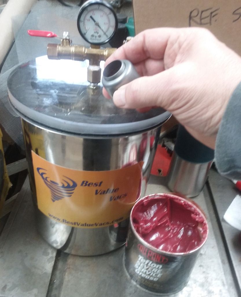
Here's a video (not mine) on this general subject showing the steps in this process:
Moses' reply and our exchange can be found by clicking the quote link:
-
Note: The link quote below ("Rebuilding the Jeep Ross TL Cam and Lever Steering Gear") is a lengthy exchange with Moses Ludel. Below is my original question from this thread, followed by Moses' response:
A question that I've been meaning to ask you concerns the wisdom, or lack thereof, in installing an aftermarket steering stabilizer, like this one made by Rancho: http://www.amazon.com/Rancho-RS97345-Steering-Stabilizer-Kit/dp/B000CP8H6W/ref=sr_1_1?ie=UTF8&qid=1457751948&sr=8-1&keywords=Rancho+RS+97345 My brother in law has a similar steering stabilizer on his '67 CJ5, and seems to like it. I've resisted installing one up to this point simply out of a desire to maintain as much originality as possible. However, it is an easily removable bolt-on item that, if it were painted black, would not be all that noticeable. If it would increase the safety margin (as it is supposed to mitigate against the dreaded "death wobble") and/or the driveablilty of the jeep somewhat, maybe it would be worth doing.
What are your thoughts on this?
Moses' reply and our exchange can be found by clicking the quote link:
-
Note: The link quote below ("Rebuilding the Jeep Ross TL Cam and Lever Steering Gear") is a lengthy exchange with Moses Ludel. Below is my original question from this thread, followed by Moses' response:
As I'm reassembling the steering gear and thinking about how to install it on the jeep, I have a bit of a problem on which I'm hoping you might be able to point me in the right direction. I had hoped it would be solved by being able to reference my brother in law's Ross box, which I now have in hand for rebuilding. Unfortunately, however, it did not answer the question at hand.
The issue is that the Pitman arms on the three V6 boxes I've now disassembled (the one from my jeep, my brother in law's, and the one from the '68) were each in somewhat different positions relative to the levers on the sector shafts. It turns out that each box had already been rebuilt at least once, as evidenced by the shafts and in at least one case, the Pitman arm having been previously replaced with aftermarket (as opposed to genuine Ross) parts. Two of these lever / sector shafts are pictured below as found, showing their significantly different Pitman arm alignments.
Though the three pairs of Pitman arms and lever shaft ends do have alignment marks, all three are in different places relative to each other on the "old" boxes - and on none of the three are the Pitman arm and sector shaft marks aligned with each other. Since all three boxes are different in terms of their Pitman arm alignments, I don't have a reliable original example to base the Pitman arm positioning on for the rebuilt boxes.
Any ideas as to how I might go about determining the proper spline alignment position of the Pitman arm? The only thing I've been able to come up with so far is to install the box on the jeep without the Pitman arm attached, then determine the center of the steering wheel travel vs. the front wheels being straight ahead, and attach the Pitman arm accordingly (an approach which seems imprecise at best).

Moses' reply and our exchange can be found by clicking the quote link:


Substitute For OEM Hanging Gas Pedal in 1967 V6 CJ
in Vintage Jeep® Vehicles 1941-71
Posted
Hi Moses, yes, the threads do penetrate through the nylon insert. I tightened the nut, then ground the threaded end of the Clevis bolt down slowly until I got to the surface of the nylon.
I'm pleased to report that there is no contact between the thin lock nut and the floor mat (though it's close).
Thank you again for all your help and advice on this project, Moses! I'm happy with the way it worked out too.
Maury