

snoopy2x
-
Posts
93 -
Joined
-
Last visited
Content Type
Profiles
Forums
Blogs
Store
Articles
Gallery
Posts posted by snoopy2x
-
-
Ahmichigan, Thank you for posting the photos of the two bellcrank shaft frame brackets. That's the first time I've seen examples of the earlier and later brackets directly compared like that.
The fact that the smaller threaded portion of the bellcrank shaft and retaining nut are the same size on both the earlier and later brackets (as is visible in your last photo) probably provides a clue that the reason for increasing the diameter of the bellcrank shaft in later models did not stem from a need to increase the shaft's bending or tensile strength. The more likely reason the Kaiser engineers upsized the bellcrank shafts from 7/8" to 1-1/8" was to provide a larger-circumference shaft that would accommodate a greater number of needle bearings through which to distribute the rotational load of the bellcrank - as those needle bearings are the components that tend to wear out and fail first in the OEM bellcrank setups.
In any case, thanks again for the photos, and best of luck with your project as you move forward with it!
-
Ahmichigan, congratulations on finding a nearly pristine (after blasting, at least) frame bracket to work with! I hope your project turns out well.
If you ever decide to convert your steering bellcrank to a modified tapered roller bearing type, I believe you'll find this mod to be a very substantial improvement over the original factory setup. The tapered roller bearings themselves are of course far more robust than the relatively delicate and much smaller needle bearings that were used on either the 7/8" or 1-1/8" versions of the factory bellcrank assemblies. This photo depicts one of the modified setups as made by Mcruff on the Early CJ-5 forum:

For comparison, a reproduction OEM-type bellcrank needle bearings and shaft kit (this is the 1-1/8" diameter version):

Perhaps the main advantage of the tapered roller vs. the original needle bearing setup is that - given the slight degree of rotation, wear, and stress they are subjected to inside a steering bellcrank - the tapered roller bearing assembly does not tend to loosen up like the OEM needle bearing setup typically did. Part of the reason for this is that, as Moses noted above, the castellated, cotter-pinned shaft nut on the modified bellcrank assembly cannot easily loosen like the original top-mounted shaft nut could (which was basically what caused, as pictured above in this thread, my brother-in-law's original factory bellcrank shaft to literally fall out of his Jeep - miraculously, onto his driveway rather than while he was driving it on the road). The net effect of these improvements is a nearly complete elimination of play contributed to the steering system by the bellcrank assembly.
When it first appeared several weeks ago, I read your eWillys post on the installation of a Hudson steering box with great interest. For some time I'd considered trying to find and install a Hudson steering box on my '67 CJ-5, but ultimately decided several years ago to restore the original Ross steering gearbox as thoroughly as possible instead, which I was able to accomplish with a great deal of Moses' help as documented in this thread:
Again, best of luck with your bellcrank project!
-
Hi Ahmichigan and Moses,
As Moses mentioned, I have one of the tapered roller bearing modified bellcranks on my '67 CJ. Mine was built by Lawrence Elliott, who to the best of my knowledge was the original designer of this particular mod. It has been an extremely successful modification, with no downside issues at all that I've discovered. Lawrence is in his late 80's now and I don't believe he's still machining, as he told me a few years ago that mine is one of the very last modified bellcranks he made.
However, as noted above in this thread, one of the members on the Early CJ-5 site, a very talented machinist who goes by the forum name of Mcruff is now producing his own version of this mod based on Lawrence's design: http://www.earlycj5.com/xf_cj5/index.php?threads/steering-bellcrank-rebuild-qusetion.129680/#post-1395299 My brother in law Fred, whose Jeep spawned this discussion, has had one of Mcruff's modified bellcranks on his '67 for the past two years, and has likewise been very pleased with it.
Regarding your question about possibly modifying the frame bracket, I'm not sure whether or not the frame brackets for the two shaft sizes are different. If they are, and you're unable to find an original bracket that accepts the 1-1/8" diameter pin, I wonder if Mcruff might be able to modify a 7/8" pin diameter frame bracket (though they are expensive, I believe take-off's are still available from Willys Jeep Parts in Yuma, AZ: https://www.willysjeepparts.com/Bell_Cranks_B.htm ) to accept a 1-1/8" dia. pin, reinforce it if necessary, and build a tapered roller bearing bellcrank setup to work with it. The tapered roller bearing modified bellcranks I've seen were designed to work with the 7/8" shaft, but maybe its possible to use different bearings to match the larger shaft. I would be glad to get you in touch with Mcruff directly if you'd like to talk with him.
I hope this is helpful! Just let me know if I can be of any further help as you explore options.
-
Hi Moses,
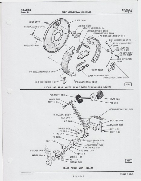
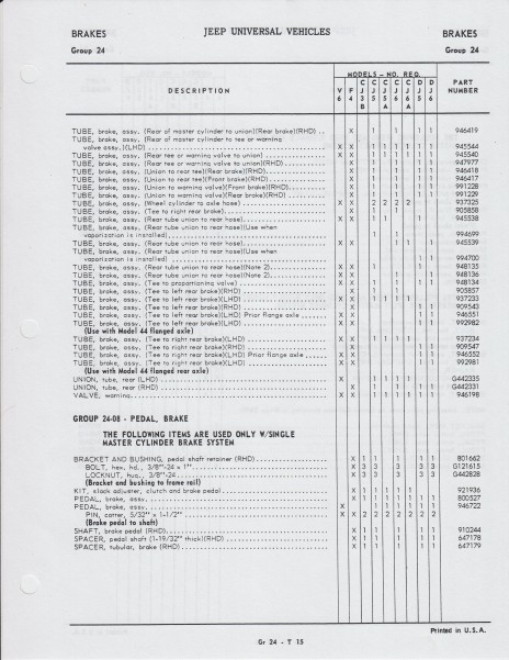
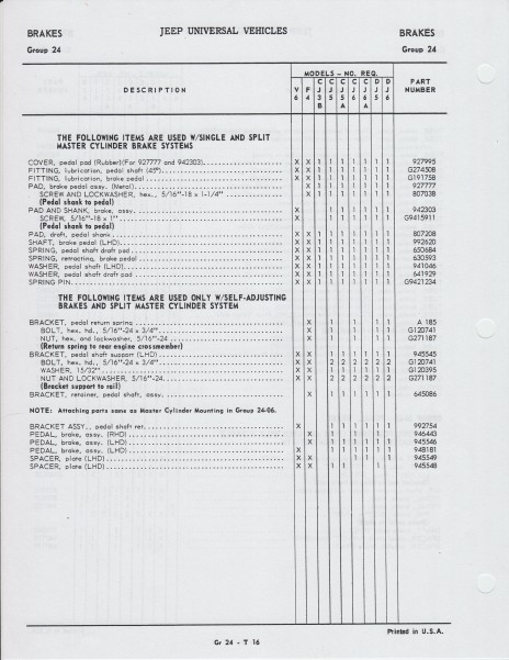
Well, it took me awhile, but I eventually found someone with an AMC 1971 Universal Parts List, and he was kind enough to scan and email the relevant pages.
Below are those including the brake arm from my Kaiser Jeep 1966 Parts List, as well as the pages from the '71 list. From what I can tell, it doesn't appear that the brake arm pushrod stud had a separate part number in either case. Do you notice anything along those lines that I didn't?:
1966:

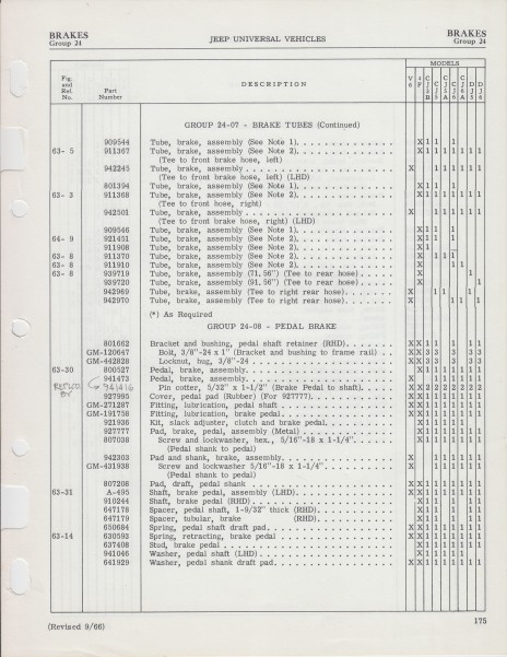
1971:
-
That's an interesting thought, and is certainly a possibility. I don't know that Fred or I have an OEM bellcrank shaft to compare to the one from the kit, but maybe another member reading this does, and could provide a comparison.
Thank you again for your help with all of this, Moses!
-
Thanks very much, Moses, and I've sent Fred a link to your excellent analysis above. I asked him if the threaded part of the bellcrank pin that came with the kit had a hole drilled through it to accept a cotter pin, and he said it did.
I can understand his and his mechanic's confusion. While the bellcrank pin has that hole, the self-locking nut (which resembles a castle nut, but has narrower slots) would not allow for the installation of a cotter pin through it without modifying the nut by widening the slots. It sounds like maybe the manufacturer of the bellcrank repair kit he purchased started out including a castle nut that would allow the insertion of a cotter pin, then switched to a self-locking nut at some point during production - but did so while continuing to provide bellcrank pins with a cotter pin hole drilled through them.
In any case, Fred has already purchased an NOS bellcrank and the Timken tapered roller bearings needed to have a custom bellcrank machined, like the ones shown in my post on the 8th. That custom unit will likely be installed later this month, and will hopefully permanently solve the issue.
-
Your comment about self-locking nuts above got me to thinking about the shaft nut in the kit Fred used. Looking at the images shown in the link ( https://walcks4wd.com/bell-crank-kit-78-2a-3a-3b-cj5.html ), I wonder if the shaft nut that came in this kit, which visually correlates with Fred's description of having very narrow cotter pin slots, could actually have been intended by its manufacturer to be a self-locking nut, rather than a castle nut?
Here's an enlarged image of the nut shown in one of the photos on the link:

-
I just spoke with Fred, and he had a (different) mechanic put the jeep up on a lift today to try to figure out exactly what caused this failure. It appears that the mechanic who installed the mount and bellcrank assembly a couple of years ago made two separate mistakes during the installation.
First, no cotter pin had been installed through the castle nut at the top of the pin. In fact, the mechanic who looked at the jeep today had to slightly grind some of the "crenelations" at the top of the castle nut in order to make them wide enough to accept even a small-diameter cotter pin.
Second, the previous mechanic had also overtorqued the pinch bolt to the point that it stripped the threads. Though the bolt was still in place, because the threads were stripped inside the nut, it was no longer capable of maintaining the necessary tensile "pinching" force on the pin across the slot in the mount.
As far as the parts used in the 2016 installation, the bellcrank was NOS. The bellcrank shaft kit used was one that should have been (to the best of my knowledge) the correct version for Fred's jeep. His is an early 1967 CJ5 built in November of 1966. Here's a link to the rebuild kit he bought (note the narrow slots in the castle nut): https://walcks4wd.com/bell-crank-kit-78-2a-3a-3b-cj5.html
I don't know for sure whether or not any parts were lost, but from his description it sounded like Fred still has all of them.
Moving forward, Fred has decided to have a modified double tapered-roller-bearing bellcrank (like those linked to above) machined and install it as soon as possible. His reasoning is that this mod will not only add a greater margin of safety, but will also result in a more easily maintainable bellcrank assembly that's less likely to loosen over time and cause unwanted play in the steering system.
Fred certainly realizes that he was very, very lucky indeed that the bellcrank pin fell out when and where it did. The consequences could have been truly disastrous if it had happened at speed and/or in traffic, which he had been very shortly before it failed. That someone was looking out for him seems, to both he and I, to be quite obvious!
-
April 8, 2018 (almost 2 years after initial posts above)
My brother in law Fred had a significant failure occur in his 1967 CJ5's steering system today. It could easily have been catastrophic if it had happened while he was on the road, instead of minutes later as he was pulling the jeep into his garage. He was extremely fortunate, to say the least.
The shaft of the same steering bellcrank pictured above (in 2016) literally fell out onto his driveway this afternoon, immediately disabling the steering. Based on his photos below, it appears that the pinch bolt that clamps the mount around the bellcrank shaft must have loosened itself over time - possibly to the point that it actually fell out(?) - and the nut on the top of the shaft likewise worked itself loose. Once both were gone, the shaft dropped out of the mount.
Fred and I had been concerned about this possibility, as mentioned in the first post in this thread a couple of years ago. In an effort to ensure that preventative measures were properly taken, Fred subsequently had the frame mount replaced and the bellcrank assembly re-installed by a local mechanic who supposedly had experience with older jeeps. Given what just happened, however, it's highly questionable whether or not that work was performed correctly.
Fred sent these photos he took earlier today:


Needless to say, Fred's a bit shaken up by this (and so am I!) If you have any questions, I'll be glad to relay those to him and post his answers.
- Do you have any thoughts in terms of forensic analysis?
- Also, is there anything you would recommend be done in order to prevent a recurrence, beyond what you already suggested above?
I'm wondering if Fred should consider upgrading to one of these modified bellcrank assemblies:
....or one of these similar modified bellcranks by one of the Early CJ5 site members:
-
Moses, your theory very well may be correct. The brake arm and the associated pin may have been differently numbered parts in the Kaiser Jeep Parts List. If so, this would explain the apparent discrepancy that the brake arms with the earlier smaller pins have the same part number as those with the later larger pins.
Thanks very much for your feedback!
-
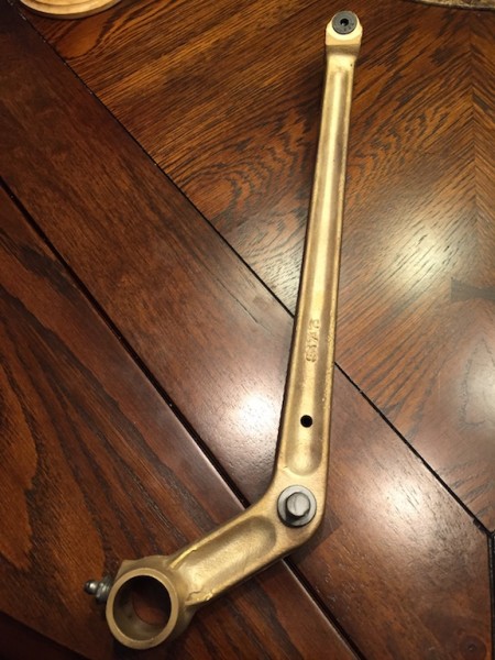
I asked the machinist working on the bronze arm if it was cast or forged, and he's pretty certain it was forged, as there are no inclusions as would be expected with a casting. He also said it is definitely solid bronze, as opposed to being plated.
As best I can determine, the CJ5 V6 brake arms were a one-off modification of the earlier brake arms used on other CJs and the M38 and M38A1. As NOS brake arms for the V6 are no longer available, a good fix for worn arms is to have them bushed. As you're well aware, the inevitable wear to the inside diameter of these arms causes brake pedal side-to-side wobble. The bronze bushing in the '71 brake arm isn't factory, but was installed as a repair to correct this problem.
Below is the (dirty, still unpolished) bronze brake arm from the '67 (top) and the one from a '71 (bottom). Like the M38A1 brake arm, the one from my '67 has the smaller pin for the early single-reservoir master brake cylinder. The one from the '71 has a larger-diameter pin to accommodate the later double-reservoir master brake cylinder. This pin is a longer, larger diameter one-piece pin, rather than a sleeve pressed over a smaller pin.![[IMG]](https://forums.4wdmechanix.com/index.php?app=core&module=system&controller=redirect&url=https%3A%2F%2Fwww.beamingpix.com%2Fimages%2F2018%2F03%2F21%2FBrake-Arms-1.jpg&key=d0ce94de1ba160f581225df1118d98a6b5663ee9a772d33bce954082c6a3a5ae&resource=1)
However, despite the significant difference in the master cylinder pins, which are more or less specialized rivets permanently attached to the arms, these two brake arms have the same part number, 941416. Why Jeep would make them with two very different pin sizes but not change the part number is an interesting question.
Maury
-
The guy installing the bushing for me is an experienced machinist, and he had the same question about it possibly being plated, but concluded after some additional investigation that it is a solid bronze cast piece. I was intrigued by your thought that the bronze arm might possibly be a leftover M38A1 brake arm, and did a bit of investigation about this possibility.It turns out that though they are indeed very similar, the M38A1 brake arm is not identical to the CJ5 V6 brake arm. The two have different part numbers as well. Below is a shot of an M38A1 brake arm above a (cast steel) brake arm from a '71 V6 CJ5. As you can see, the "bends" in the castings are slightly different between these two parts:

Note that the brake arm from the '71 has exactly the same shape, and also the same part number as the one off my '67 jeep. However, like the M38A1 brake arm, the one from my '67 has the smaller pin for the early single-reservoir master brake cylinder. The one from the '71 has the larger-diameter pin to accommodate the later double-reservoir master brake cylinder. (Why Jeep would make brake arms with two different pin sizes but not change the part number is a mystery to me.)Did any other thoughts occur to you as to why the one on my '67 was made of bronze? As you say, there must be a reason, but so far it has been an elusive one to figure out.Maury -
I sent what I believe to be my jeep's original brake arm to a machinist in Alabama who rebushes a lot of them for members of the Early CJ5 site. As it was being cleaned and then glass-beaded, he realized that unlike any others he had previously seen, this brake arm is made of bronze rather than steel. He started a thread about it with this photo: http://www.earlycj5.com/xf_cj5/index.php?threads/strange-brake-arm.129750/
Apparently, these solid bronze brake arms have been found on a number of '66 & '67 CJ5s (http://www.earlycj5.com/xf_cj5/index.php?threads/brass-brake-pedal-arm.89095/#post-951636), so it's likely an OEM jeep part.
My question is, why would Kaiser Jeep have made some brake arms out of bronze instead of (less expensive) steel in the first place? Do you have any insight on that?
The vast majority of the wear on mine was to the (also likely original) steel cross shaft, rather than to the inside diameter of the bronze brake arm pivot. I've always thought that steel is harder than bronze, and would think that the bronze would therefore wear out faster than the steel. Am I wrong about that?
Maury
-
EchoWars, thanks, and I agree with both of your points.
As for the second, having the same thought, I bought a bunch of extras of those particular filter elements on closeout. As I only drive my jeep 1000 miles or so a year, mostly on paved roads, I figure I can get by for another 30+ years using the air filters I have on hand. And since I kept my original stock oil bath air cleaner unit, I could always go back to that if I (or my son, who will eventually inherit the jeep) ever need to.
-
My goals with this project were:
1) to eliminate the problem of oil dripping onto my intake manifold when removing or installing the oil bath air cleaner (which I learned the hard way was all too easy to do);
2) to resolve this issue without changing the external appearance of the original air cleaner housing, and
3) to accomplish both of the above while still providing an adequate amount of low-resistance flow of filtered air to the engine.
This mod achieved all three, so I think it was worth the effort involved. Removing the paper filter element is as simple as taking off the upper air cleaner housing and lifting out the cartridge.
As with all of the rebuilds and mods I've done on this jeep, I really enjoy the challenge of creating a workable solution to a problem like this!
-
Yep....both the top and bottom of the 170 CFM filter element seal tight against the two stainless steel discs installed in the OEM oil bath housing.
Glad to finally have this project done!
Maury
-
Note: I've just updated my original post above to show how I improved the initial modification to use a 170 CFM paper filter element, rather than the 90 CFM filter I'd first used.
Hope this is helpful to those considering converting their oil bath air cleaners to use a paper element.
Maury
-
HI Moses,
I have some general questions for you re. oil bath air cleaners vs. paper filters.
I've read that oil baths, while they work well in terms of removing particulate matter from the air, tend to become more restrictive as the air flow through them increases. However, I've not yet found any conclusive data in terms of a CFM comparison of an oil bath air cleaner vs. a paper filter type.
The paper filter manufacturers, e.g. Wix, do publish CFM figures for each of the filters the make - but do those figures represent an actual maximum air flow for a given filter, and is that figure generated via a calculation of the filtration / surface area of that paper element?
When I chose the Wix 42011 filter for this conversion, I selected it based on 1) the fact that it fit well into the modified oil bath housing, and 2) that it is commonly used on similar sized (i.e. 225 c.i. 6-cylinder) motors, as well as some larger V8s. That particular filter also had the highest CFM rating (90) of the various filters that were within the dimensional diameter and height ranges I needed.
In 1970, Kaiser jeep shifted to a paper filter for the 225 V6. I checked the data for those particular filters on the Wix website and found that they were shown as being 155 CFM. My jeep, even with a modified cam that probably somewhat increases the air flow required compared to a stock motor, seems to run quite well on the 90 CFM filter I just installed. But would it run even better on a less-restrictive 155 CFM filter like the ones used on the 1970 V6s - or a filter with an even higher CFM figure? Conversely, could I have used a paper filter with a significantly lower CFM "rating", and still have achieved good results?
In other words, in selecting a paper filter to replace an oil bath type, is there a "right" way to approximate an air filtration CFM range required by or recommended for a given motor displacement?
Thanks, Moses, and I look forward to hearing your thoughts. This project, as they all seem to be, is yet another learning experience!
Maury
-
This post follows a recent post by Tim E on the EarlyCJ5 site describing his conversion of the later-type (late 1967-'69) oil bath air cleaner to accept a paper filter element. That thread can be seen at V6 Oil Bath To Paper Element Conversion.
Below is a description of my conversion of an early-type (1966-early '67) oil bath air cleaner to a paper element. I actually completed this project awhile back using a slightly different approach than Tim did, but am just now getting around to writing up this post.
I've had the original oil bath air cleaner on my early '67 CJ5 since I bought it in 2009, and until recently, I had no plans to change that. Oil bath air cleaners do a fine job of removing dust from the incoming air, and especially considering that it is original to the jeep, I saw no reason to do anything different.
Then, about a year ago, the engine was rebuilt and completely repainted. At some point following the engine rebuild, when taking the oil bath off or putting it back on, I apparently accidentally tipped it just enough to drip a little oil onto the top of the intake manifold. After the oil sat there for awhile, it had the effect of peeling off some of my brand new engine paint. To prevent this from happening again, I decided to give this mod a try.
After looking at the air cleaner closely and searching around online for different paper filter options, I was fairly sure I'd figured out a way to make this modification work without altering its original external appearance. However, since I wasn't 100% sure it would work, rather than modifying my original oil bath air cleaner's housing, I looked around for awhile to locate a matching '66-'67 air cleaner, and eventually found one. Having both a modified and an intact original oil bath air cleaner is what I'd actually prefer anyway, just in case I or someone else in the future ever decides to change it back to the original oil bath type for some reason.
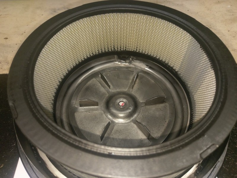
The first task was to use a jigsaw / sabre saw to cut the bottom out of the upper portion of the air cleaner housing. Measuring from the top flange of the housing, I left about 1-1/4" of the metal cylinder in place below it. This metal is fairly thin, so it only took a couple of minutes to make this cut. Once the bottom was cut off, there was a metal screen that was easily removed by hand. The cut-off metal edge was smoothed using a hand file.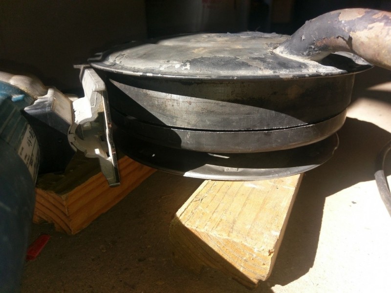

The old paint was removed from the lower housing by using various wire wheels on a drill, rather than by blasting. I didn't want to blast it because I was concerned that some of the grit might get caught in between the joints in the metal, get into the cavity, and later find its way into the engine.
With the upper housing cut open, it was possible to fairly accurately measure the inside surfaces and pick out some different paper filter elements that might work.
On the Wix Filters website, there's an option to sort through all the air filters they make by their outside dimensions. After carefully measuring and then actually experimenting with a few different filters, I finally settled on the Wix 42011. This filter is rated for 90 CFM, and is very common, as it was used for many years in various Chrysler-Dodge-Plymouth vehicles with the slant 225 straight 6 engine, as well as in some V8 applications.
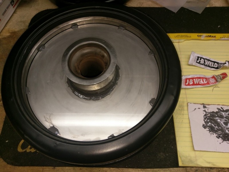
Continuing with the modifications on the upper housing, an angle grinder was used to grind the bottom of the PCV tube more or less flush with inside surface of the housing. This grinding no doubt weakened that joint, so after blasting, I used some JB Weld steel reinforced epoxy to strengthen it.
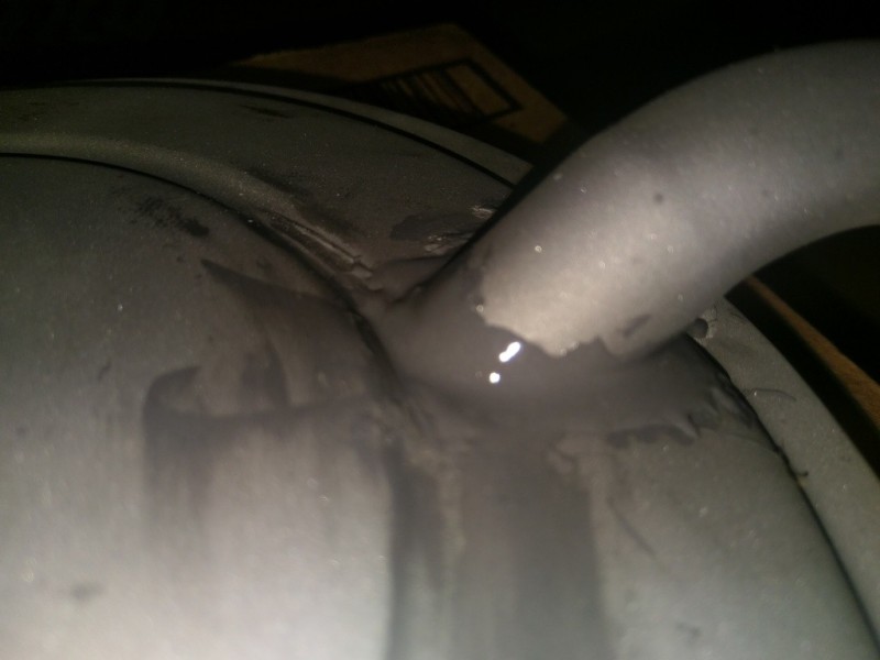
I wanted to make sure the PCV system would continue to function normally after the original housing was modified. The way the PCV system on the Dauntless works, in a nutshell, is that filtered air is drawn out from the air cleaner through this tube, down through the crankcase of the engine, then out through the PCV valve and is pulled by vacuum into the intake manifold, where the crankcase fumes are burned off.
One difference between the early type and the later type oil bath air cleaner is that the early type had a cone-shaped bottom flange (see photo of screen removal above), rather than the flat flange the later type had. The solution I ultimately came up with was accordingly a bit different than Tim's.Rather than mounting a flat circular flange at the bottom of the shortened upper housing as Tim did, I used a stainless steel ring attached inside the upper housing to provide a level surface for the top of the paper filter element to seat against. This ring also keeps the PCV tube's opening from getting blocked by the top of the paper filter element. Because the ring is mounted up near the top of the inside of the upper housing, the paper filter element used is quite a bit taller in this version.
The ring is 14-gauge stainless steel with a 8-3/4" outside diameter and a 6-1/2" inside diameter (total shipped cost was about $18 through eBay seller Lumberjack1983). When mounted, there is sufficient clearance between the PCV tube's inner opening and the ring for air to pass through the tube. A small notch was also ground into the inside edge of the ring at the tube to ease the flow of air through it. I used Loctite RTV to seal the outside edge of the ring to the upper housing, then used JB Weld epoxy to make "spot welds" around its perimeter to permanently secure it in place. (After the epoxy cured, I filled the areas in between these "spot welds" around the outside of the ring with RTV.)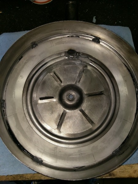

To help ensure a good seal between the filter against the cone-shaped surface inside the lower housing, as well as to get the necessary height differential between the lower and upper housings when installed, I picked up a 5" silicone pipe flange seal on Amazon (Silicone Flange Gasket, Ring, Red, Fits Class 150 Flange: Industrial Gaskets: Amazon.com: Industrial & Scientific). I "glued" this silicone ring to the inside surface of the lower housing using the process described here (which seems to have worked well):
What glue do you use to glue silicone rubber to steel
The exterior of the air cleaner housing was painted with VHT gloss black epoxy spray paint. I've used this particular paint in the past and have consistently had excellent luck with it. It requires no primer, and has a sheen that's very similar to the original air cleaner's black paint. (Note, however, that if using this paint and you decide to apply additional coats after the first hour, you'll probably need to wait quite a bit longer than the 7 days indicated on the can for the epoxy to cure completely first....based on experience, I'd recommend waiting at least 2 or 3 weeks.)
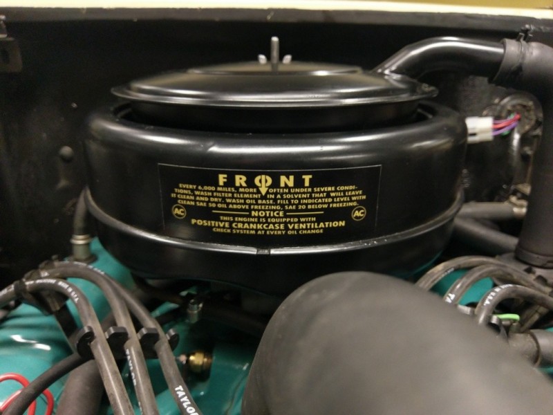
Last, I applied a new air cleaner sticker to match the original, available on eBay from seller jfranzl48.
The installed modified air cleaner looks identical to the original, and the engine (still) runs just fine with this paper filter setup. I haven't found a need yet to adjust the carb for any differential in air flow there may be between the oil bath and the paper filter element.
And best of all....No More Drips!")
UPDATE 6 / 2017:
TimE on the Early CJ5 forum corresponded with me about this air cleaner conversion project following my initial post above. During that conversation, he told me about another paper filter he'd found on the Wix website with a higher CFM rating. I hadn't located this paper element during my own search, as I'd been looking at filters in a different range of dimensions.
The paper filter I'd used above, the Wix 42011, is rated for 90 CFM. The filter Tim found was the Wix 46022 (for a 1981-82 Toyota Starlet), which is rated at 170 CFM. Though it's both shorter and smaller in diameter than the 90 CFM filter, it's also much thicker, which is clearly what allows the significantly higher CFM rating (due to having more paper surface area).
I decided to try to figure out a way to use the 170 CFM filter instead of the 90 CFM element I'd initially used. The 170 CFM filter exceeds the specs of the OEM paper element used on the 1970-71 Dauntless engines, which was rated at 155 CFM. Though at lower RPMs, the 170 CFM filter wouldn't result in much if any improvement over the 90 CFM filter, at higher RPMs it should deliver the needed volume of air with less resistance.
In comparing a few different brands of the 170 CFM paper element, it turned out that the ACDelco A2980C was a bit more robust than the Wix version, as it incorporates an expanded steel mesh outer surround, while the Wix lacked this feature.
With one of the ACDelco A2980C filters in hand (about $11 on Amazon), it became clear that with the addition of another stainless steel disc in the lower housing of the oil bath air cleaner, this higher-CFM filter would work with the modifications I'd already made to the upper housing. In order to modify the lower housing to make it fit, I ordered a 1/8" thick, 9-5/8" OD and 3-17/32" ID stainless steel disc on eBay (from the same seller I bought the first disc through, Lumberjack1983):

The new lower disc sits on the horizontal ledge just above where the lower housing is stamped "oil level":

After first removing the silicone pipe flange installed above (which was difficult, as it turned out that the silicone "gluing" had worked very well!) and cleaning everything thoroughly, I epoxyed the disc to this ledge using steel-reinforced JB Weld, and also placed eight epoxy "spot welds" around the disc's perimeter to secure it to the inner steel bowl of the oil bath housing:
Loctite Superflex RTV was used to seal the remaining outer edge of the disc. It was also applied around the inside, just to ensure that any pinholes that might have existed in the epoxy joint there were sealed:

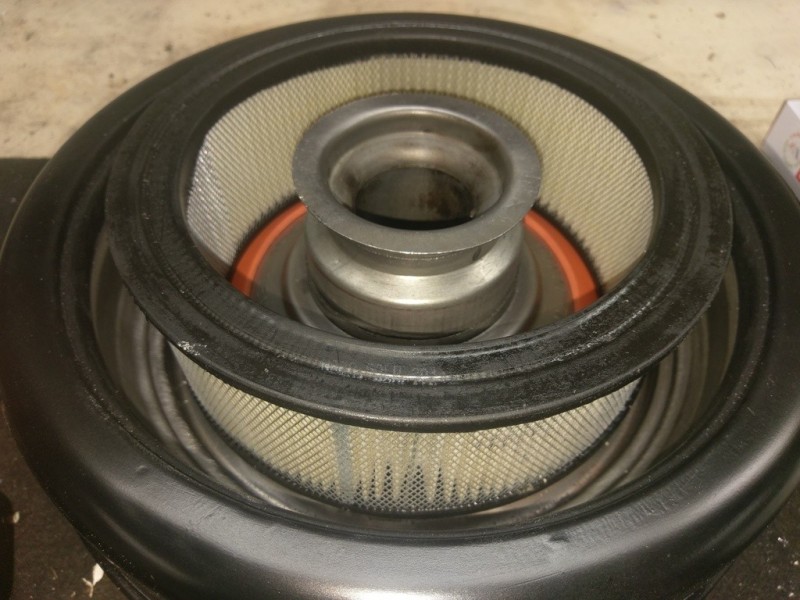
Here's how the upgraded filter fits on the modified lower and upper housings:
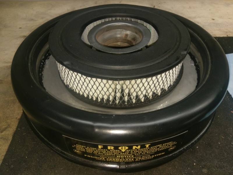

The Dauntless runs great with the revised setup, and the re-modified original housing with the 170 CFM filter still appears to be stock when it's installed:
Thanks again, Tim!! :-)
-
Monty, the routing of the wire as shown in this photo is the same as the original factory routing in the '66 and '67 CJ5s with the one-speed electric wipers. The noticeable slack in the wiring harness is there in order to allow the windshield to be folded down.
You'll need a grommet to fit the hole in the dash panel (mine is 3/4" dia.) with a 1/4" hole in the center. Here's what I used:
See the note at the end of the wiper motor rebuild thread for the wiring clamps that attach the harness to the windshield frame.

-
(Yep, caught it, Moses!
") )
)
Monty, the two red wires are the main power wires running from the switch (assuming you still have an original working switch - for photos of an original, see the link Moses included above) to each motor. The brown is the "parking" power wire, and the blue is the ground.
This post on the EarlyCJ5 site, as I mentioned in the thread on rebuilding the American Bosch wiper motors, references this original wiring arrangement:
http://www.earlycj5.com/xf_cj5/index.php?threads/wiper-motor-question.107558/#post-1318035
As is also mentioned in that thread, Walcks 4WD can make a repro of the wiper wiring harness, which is separate from the main harness, for you. If your switch is not original, you could have Walcks install blade connectors on the new harness, and/or bridge the two main power wires to allow you to use a different switch. The original switches are no longer available.
I'll be glad to try to answer any questions about this that I can!
Maury
-
After reading a post on the EarlyCJ5 site that mentioned the name Norton Young, having no idea who he was, I googled him and found the following reference excerpted from the book Jeep CJ 1945-1896, by Robert Ackerson:
"Most Jeep enthusiasts regard the production figures recorded by Norton Young, an engineer who worked at the Toledo plant, as the most accurate. Jeep historian Charlie Weaver worked with Norton Young's handwritten records and transformed them into electronic form, making them available to jeep hobbyists worldwide."
I immediately recognized the name of Charlie Weaver because ironically, I actually visited Charlie at his home in Winston-Salem, NC back in 2008. Here's a link to a copy of a post I wrote back then on the G503 site about the story I learned from Charlie that day:Maury
-
Thanks for the kind words, Moses!
One thing I forgot to mention, for the benefit of anyone else who decides to replace their wiper wiring harness, is that I was able to locate an excellent replacement for the plastic wiring clamps used to attach the harness to the inside of the windshield frame. Visually, they're almost a dead match for the original plastic clamps used by Kaiser Jeep in the late 1960s, but these are made of nylon rather than plastic.
The replacements are Ancor 402312 Marine Grade Black Nylon Cable Clamps (5/16" dia.). I found them on eBay, but I'm sure they're available from a number of different sources. Here's a photo showing one of the surviving original plastic clamps from my 1967 CJ5 on the left next to one of the new Ancor clamps on the right:

A total of 8 of these clamps were required on my jeep. I used #10 x 1/2" stainless steel Phillips panhead sheet metal screws, which are very close in appearance to the original screws, to attach the clamps to the windshield frame.
-
After successfully lub'ing the wiper shafts, I moved on to reassembling the motors. The first step was to apply the Mobil electric motor bearing grease on the original bronze bushings:
![[IMG]](http://www.beamingpix.com/images/2017/09/11/22.20170127_173018_zpscgadeytq.jpg)
![[IMG]](http://www.beamingpix.com/images/2017/09/11/23.20170127_172226_zpskf05uhxj.jpg)
The motor housing parts are all "keyed" where they fit into one another, which is helpful in putting them back together correctly. Given that there was some rust inside one of the motors where it had leaked sometime during the past 50 years, I decided to go ahead and seal the casings parts during reassembly. Once I'd confirmed how the parts fit together, I used the Loctite Superflex sealant to create a watertight seal between them.
One useful trick in reassembling these WWF motors is to temporarily hook the brush wires back behind the small metal brush housings in order to allow placement of the motor shaft correctly within the front portion of the housing. The Loctite was applied to the front end of the motor housing at this point as well:![[IMG]](http://www.beamingpix.com/images/2017/09/11/24.20170127_172301_zpsogpp7kjl.jpg)
Once the shaft is inserted to the point shown in the photo below, the brush wires were "unhooked" to allow the brushes to contact the commutators properly.![[IMG]](http://www.beamingpix.com/images/2017/09/11/25.20170127_172359_zpsrtcmgzjz.jpg)
After fully reassembling the motors themselves, the next step was to reassemble the gearboxes. I cleaned any visible grease off of the ends of the motor and wiper shafts, then reassembled the gearboxes using the Bosch tool grease. The cleaned parking circuit connectors (both the semicircular piece attached to the lid, and the copper alloy connector "button" over the small coil spring) were coated with Deoxit Shield. Note that the pin in the arm connecting the gear to the wiper shaft is placed in the 120-degree hole, as originally configured.![[IMG]](http://www.beamingpix.com/images/2017/09/11/26.20170128_151112_zpsbcevr64r.jpg)
On one of the motors, the insulation on the small wires connecting the parking circuit to the power supply showed signs of blackening / slight burning. It's possible that the insulation been worn through from vibration over time, and the wires had shorted at some point. Using an ohmmeter, I was able to confirm that the wires themselves still tested okay in terms of resistance, so I used shrink wrap to re-insulate them before putting everything back together:![[IMG]](http://www.beamingpix.com/images/2017/09/11/27.20170128_153733_zpscjudm43d.jpg)
![[IMG]](http://www.beamingpix.com/images/2017/09/11/28.20170128_154241_zpsrdygsbym.jpg)
After running a thin bead of the Loctite Superflex around the edges of the gearbox lids and reinstalling them, the motors were ready for testing. I'm happy to say that both perform properly and run very quietly. The excess Loctite was cleaned from the housings, and the motors were repainted using using VHT epoxy black gloss spray paint.
The motors were then reinstalled on the windshield frame and connected to the new wiper wiring harness from Walcks. Note that the original factory setup used an unfused 12v power wire from the ACC side of the ignition switch to the wiper switch. I opted to replace this original wire with a new one I made with a 10-amp inline fuse added into it.
The newly rebuilt motors mounted on the windshield frame:![[IMG]](http://www.beamingpix.com/images/2017/09/11/29.installed_zps1twgfksi.jpg)


1956 Willys CJ3B Rebuild and Restoration
in Vintage Jeep® Vehicles 1941-71
Posted
Hi Mike,
Just to consider as you're looking for a replacement timing cover....you may have read that the OEM-designed oil pumps for the 225, which are integral to the timing cover, were not particularly well reputed and tended to wear out over time. Though at $450 it's not cheap, TA Performance makes one for the 225 which includes a high-volume, adjustable-pressure oil pump that's designed to reduce the load on the camshaft: http://www.taperformance.com/proddetail.asp?prod=TA_1533
In addition, particularly since you're removing the old timing cover anyway, you might think about replacing the original type timing chain and gears with a double-roller set (like a Cloyes Model 9-1132 Street True Set). Besides being yet another way to spend even more of your money on your Jeep, it provides a smoother and quieter timing chain setup.
I have both of the above on my Dauntless and have been very pleased with them.
Maury