


Moses Ludel
-
Posts
4,447 -
Joined
-
Last visited
Content Type
Profiles
Forums
Blogs
Store
Articles
Gallery
Posts posted by Moses Ludel
-
-
Nice install and welds. This kit does not "sandwich" the tubes with an upper and lower truss. The strength of these upper trusses and C-gussets is tremendous. They make up for the factory tube weaknesses. These beam axles often came to the dealership with excessive negative camber, likely from factory jig welding, the inherent welding (heat) risks or even from being tied down too tightly on a car transport. Off-road pounding on rocks with oversized tires will bend these axle tubes. Yours won't. Ever.
Welded right, in "stitch" fashion with thorough cooldown before welding adjacent sections, the camber should be on specification despite the extensive heat exposure. Once together, a camber check will answer that question.
Moses
-
53HiHood...I did some homework...The attached schematic is for your chassis wiring (Rubicon with factory lockers only) and helps explain the dash lamp system. It's complex. The dash lights are activated by the control module and interaction with the lockers. You may have cleared the issue with the front axle/locker wiring fix. You'll see the relationship in the wiring diagrams.
If the problem returns, a sticky 4x4 mode switch is possible, though I would look for either debris in the transfer case or possible parts misalignment from wear. If you've heard unusual "noise" in the transfer case, drain the transfer case and sift through the lubricant for signs of chain or case (aluminum) wear.
The mode switch could be malfunctioning intermittently. If the wiring and mode switch are accessible, jump or bypass the switch to complete the circuit and see if you get a distinct 4WD dash light with the key turned ON.
If that doesn't do it, there are several other components involved with the dash light signals. Review this PDF of the wiring circuits for your 4WD (transfer case) and factory air locker indicator lights:
TJ LJ Rubicon Transfer Case Switch.pdf
Moses
-
Jeepdog...You photos are very helpful. Assuming that the MSD ignition is firing optimally, the plugs are showing every indication of a rich condition. The BBD without computer feedback could be jetted improperly (combined jets and metering rods) for a 258 cubic inch engine.
Checking spark plugs for a rich mix requires testing the main jets on the carburetor's high speed circuit. You do this by running the engine at or near wide open throttle then quickly shutting the engine off. This can be done in a lower gear since the test is strictly rpm and throttle position related. Hold the throttle open steadily for a bit without over-revving the engine. Inspect the spark plugs under that condition. To eliminate confusion, the plugs should be relatively clean to start this test.
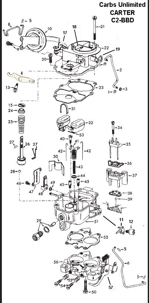
The Carter BBD was popular on Mopar V8 engines. Considering the cubic inch displacement of these V8s, the carburetor jetting can vary widely. The base mounting pattern is the same as a 258 application. If there is a tag or stamping I.D. number on the carburetor, let's verify the original application. Otherwise, you'll need to disassemble the carburetor again and verify the jet sizes and metering rods.
If jets are right, confirm that the carburetor is assembled correctly on the metering circuit. Note check ball(s) placement and make sure any check balls are in their correct locations. If this carburetor was rebuilt professionally or DIY, go over it carefully and verify all the linkage adjustments, including the choke pull-off. I have a lot of carburetor data if we can determine the BBD's original application.
I snagged this schematic drawing (courtesy of Carbs Unlimited) of a typical Carter BBD carburetor without a feedback system. Note the check balls at positions #39 and #28 in this illustration. Check balls and their size are critical:
Here is my rebuild of a factory Jeep 258 feedback carburetor. You can get instructions for your non-feedback carburetor from either a shop manual or a carburetor rebuild kit for your specific application carburetor:
Your photos also reveal the way an inline six distributes fuel. This is a graphic example of the outer cylinders running leaner than the inner cylinders. Assuming that the compression is normal at all six cylinders, this lean/rich condition is typical of inline sixes with a center mounted carburetor and uneven length intake runners. Check the engine's compression just to be sure it's okay.
Let's work through this...
Moses
-
53HiHood...Glad the parts for the locker came through...What trusses and C-gussets did you use? Any pics of the trussed axle housing? We just discussed trussing at this JK Wrangler exchange:
Moses
-
53HiHood...Congrats on the '06 Unlimited Rubicon LJ! Great wheelbase for directional stability. Lift kits help with the over-center clearance. You need wide wheels with negative offset to keep the center of gravity stable after lifting.
The mode switch can be an issue...You can test that readily with a voltohmmeter and shifting through the transfer case modes. Internal transfer case issues can upset the mode switch, too. Check the fuse and electrical circuit first. The mode switch typically completes the ground, check the hot side for shorts.
Let is know what you find...
Moses
-
Jason1234...Let us know how this works out. Here if you have wiring questions...Happy New Year!
Moses
-
goalie94...Ah, a Dana 30...Thought you had a Rubicon Edition with 44s. Is the Facebook Jeep a Rubicon? Or are you swapping a 30 front for another 30? (If so, your current axles are acceptable if you're on a tight budget or time constrained.) I do like the 4.56 ratios for stamina over 4.88s, and 35" tires are plenty unless you plan to drive rockpile trails like the Rubicon.
If the net cost is only a couple hundred dollars, there's a strong argument for getting the trussed axles (if the trussing was done right and housings are straight after trussing) with 4.56 gears, the wheels, tires, axles, springs and shocks. Just be sure these pieces are as represented; diplomatically ask for pictures of the trusses to see the weld quality. The quality of the aftermarket gear set installations is always a crapshoot.
Happy New Year! 2023 should be an exciting year for you and your growing family...Congrats!
Moses
-
Excellent, predicted results, you should be very pleased with your work here. I am glad to know MOOG has this part and the part number. I had previously thought that SPC was the only source, and MOOG is a known OEM brand. (There must be a substantial market for ball-joint alignment corrections on these beam axles! Not surprising.) Thanks for furnishing the part number. Expand and see my comments below...
On 12/29/2022 at 2:41 PM, goalie94 said:Alright we are nearing the end of this!
Got the Moog K100312 1.5 degree ball joint, Lined her up and installed it so only thing being effected was the Caster. Got everything buttoned up. Took the jeep in and lo and behold everything was good to go! ball joints were very similar, passengers side was a little higher but sounds like from stock its a little higher on the passenger.
Great to know MOOG has this part. Good news...
Latest dliemma I have the Metal Cloak geometry bracket installed so I could use stock control arms for now....If I am on the lowest hole my caster is around 6.0 and if I use the center hole my caster is around 4.3.
So, stock is around 4-degrees positive. This is a personal choice. 6-degrees positive will certainly work well, though I would rotate the tires regularly. In you decide to go "stock" with specifications, moving the caster forward to 4-degrees positive may throw off the toe-in setting. If the steering wheel position changes in the straight ahead position, that's a clue.
Another factor here is front driveline pinion angle. You have a double-cardan (self-cancelling angles) at the transfer case, so the only concern is the front pinion yoke joint angle. 6-degrees positive does increase this angle, which is not an issue if the angle is well within the U-joint's designed operating angles over the full range of the suspension travel. Better yet, your JK Wrangler Rubicon has a high-pinion 44 front axle, which further reduces the U-joint angle concern...Check this, anyway, it could be a factor.
Not going to worry to much about it as I am going to put slightly taller springs since the jeep has Reid Knuckles and a Flipped Drag link kit. Sounds like I should have 3.5 inches of lift and currently the jeep has a small 2.5 inch lift.
Well, this may turn out to be your answer. The longer springs will rotate the axle housing forward and reduce the axle's positive caster angle. You may end up between 5- to 6-degrees positive. If you use the 4.3-degree positive holes and install the longer springs, your caster could end up less than 4-degrees positive, which would be undesirable.
Should I be Trussing and Gusseting the jeep since at one time the axle was obviously bent?
That's clearly an option and depends on your intended use of the Jeep...As the video revealed, such an install needs to be done very carefully, as warpage will occur if not done properly. Do you have a MIG welder? The other concern is heat damage to ball-joints, differential seals and the axle tube-to-center housing seals when trusses and gussets are installed on an assembled axle. The truss/gusset company's video seems responsible, a heads up and guide.
One other factor, not mentioned, is lighting the axle lubricant on fire, which can happen if welding heat and heat transfer/dissipation bring oil to its volatility point. The presenter did emphasize short stitch welds and full cooldowns between any welds in the same area. This would help reduce risk of an oil fire within the axle housing.

This caster match-up is good, including cross-caster. Camber is higher than specification but not a deal breaker. You can compensate, as you noted, with regular tire rotations.
Note: I have SPC FasTrax alignment equipment and can measure camber. If I were installing axle housing trusses like the types shown in the video, I would rig a come-along and attempt to carefully pull out that 1-degree of camber error either before or during welding process. (With my camber gauges in place, I would install the top trusses first, keeping tension applied to hold the housing on specification. Since the error is in negative camber, doing the top trusses first would maintain correction as the housing cools. With the camber corrected, I would then weld the bottom trusses into place, making sure the camber does not change.) Tension applied throughout the cooldown period would probably work best. I would only try this while installing trusses; distorted or bent metal likes to return to its distorted shape. However, when installing trusses, you are heating the axle housing (making the straightening easier) then increasing the housing's rigidity and strength with the trusses. 1-degree is a relatively minor shift, especially at the longer axle tube side.

This would pass for "stock" settings with camber being over-negative but not extreme. Thrust angle is good for an aftermarket suspension system. Rear camber is still puzzling, you should be able to live with it, though.
If the steering gear is on high-center with the wheels pointed forward (straight ahead), these specs should be good geometry for handling, control and on-center driving. The natural return to center after corners will be good with either caster setting.
Moses
-
Well, Mike, you'd be going full circle to the original plan, certainly an option. The 700R4 with the correct drop side 208 is a prospect. The 200R4 was common for Buick V6 models. You have the BOP bellhousing pattern, which means V8 engine parallels. There may be an early '80s Olds 307 or 350 V8 powered GM car that used the 700R4. (350 diesel cars would have the Olds BOP pattern, too, and they used the 700R4.) This could provide the front end of the transmission to mate with your V6.
The output needs to be a 4WD application from a GM truck that used the 208. A hybrid transmission could be built with those pieces. GM upgrades make the late eighties (1988-up) units best. Build the transmission with those upgrades.
3.73s with 31" tires would be okay for a truck 4-speed box, especially for your planned usage. The compound low gear with your Dana/Spicer 20 transfer case would be a real asset and save clutch wear...Comes down to an automatic versus manual transmission.
Have a safe and Happy New Year as you contemplate the Jeepster project for 2023!
Moses
-
Mike M...Thought it was the SROD or RUG, not a bad approach, these were used with light-duty pickups and moderate horsepower in league with your 231 Buick engine. These transmissions have synchromesh on first through 4th/OD. No gain in the ratios, but you get overdrive.
Have you considered a truck box like the SM420 or SM465 Muncie four-speed? The common version of the older SM420 transmission uses a non-synchromesh 7.05:1 compound low gear, and the SM465 has a 6.54:1 (non-synchromesh) compound low gear. Either ratio would offset the taller low-range gearing of the Dana/Spicer 20 transfer case (2.03:1) if you plan to crawl off-road. Many did this and ran taller axle ratios like 3.73s or 4.10s with 33" tires to compensate for no overdrive. (Your tires look close to that size.) 3.73s or 4.10s and no overdrive would be tolerable on the highway. What axle ratios does the Jeepster have? 3.73:1?
As you recall, the SM420 and SM465 normally start out in synchromesh 2nd. To simplify, a Buick engine bolts to an SM420 or SM465 by using a stock Buick V6 passenger car three- or four-speed manual transmission bellhousing. The SM420 (used from 1947 to as late as 1967/early-1968 in GM light trucks) and the SM465 (1968-up) have the typical GM front bearing retainer index diameter. You could use either of these transmissions with a stock Buick V6 (passenger car) bellhousing and the correct crankshaft pilot bearing/bushing, clutch disc, cover, throwout bearing and release arm.
You would need the transmission-to-transfer case adapter, which Advance Adapters can furnish. They have the correct bearing(s) and adapter ring as well. This approach has been a mainstay conversion for as long as Advance Adapters has been in business (1971). These rugged transmissions are now getting older, and a "good used" one would need new bearings and refreshing.
The beefier and heavier duty SM465 was my choice for higher horsepower applications. I used one behind a 383 small-block Chevy stroker V8 in an FJ40 Land Cruiser magazine project vehicle...Either truck box would be overkill for the Buick 231 V6. Even the vintage SM420 is much stouter than an SROD, T14, T176, T150, NV3550, AX15 or any other Jeep light 4x4 transmission. The SM465 is much stouter than a T18/T19 truck box, more like an NP435.
Wider YJ springs are a popular upgrade for CJs. The shackle reversal kit would need to be substantially built and well conceived. If not, the front driveline, axle caster angle and other factors will be off. The shackle position, shackle length and the spring arch must be correct to maintain proper axle/caster angle over the travel range and not force the front driveline through the transfer case.
Moses
-
See comments on your note below, Mike, thanks for sharing. The Jeepster has tremendous potential—and you're finding it. Readers will be envious of the rust-free body. Wyoming and Nevada—high desert, semi-arid.
17 hours ago, Mike M said:Freakin Winter....
So, the RTS has a very similar ratio set as the T14. At least the version that Herm rebuilds and sells. Very Close. Plus, he makes improvements where he can. From what I can determine, it's a drop in. No driveline corrections or anything. Since he can't source any, I am curious as to how difficult it is to adapt the Buick and the Model 20 to a WC T5? I didn't get a chance to get in touch with him today. So the project for tomorrow is to just remember to call him about it. I realized about two weeks ago that the original 37 amp alternator is and will be pathetically under powered for added electronics, so I ordered a 78 amp from an 84 Buick Regal. A bit of wiring, and it should be peaches. EFI, Winch, SEAT HEATERS.
") . I decided not to go full bore 94amps just due to added engine load. And I figure 78 ought to do it.
. I decided not to go full bore 94amps just due to added engine load. And I figure 78 ought to do it.
The new CJ7 project drove here just fine (with the hood strapped down. It has a 4cyl/4spd in place of the original 258/T5. ??? I know,, huh. Who would DO that? Anyway, many options on engine/trans combos. I do have that 210HP/275TQ 3.8 sitting there, but that's for the Jeepster when I need it. Any suggestions on a modernish engine/OD trans capable of interstate speeds? The wife likes the hydraulic clutch in my jeep so much, she has elected to stick with a manual gearbox.
The RTS sounds like the Ford F150 transmissions offered in the early '80s? Three speeds forward plus an overdrive 4th, right? The Ford units would be in the ballpark for a bellhousing pattern and such. Is that the transmission Herm works with now?
Advance Adapters did a lot of work with the WC T5 when I was writing extensively for magazines in the eighties and nineties. They were direct distributors for the B-W WC T5 and did a lot of adaptations. Contact my friends there at 1-800-350-2223. Ask about the approaches you are considering.
I like your rear fender roll work, a nice touch! One thing I would do with the chassis is a shackle reversal kit at the front springs. This would put your spring anchor ends to the front and the shackles at the rear of the leaf springs. This makes a dramatic improvement in handling and control. The stock front shackle setup (CJs and the Jeepster) has the frame pushing the springs and front axle forward from the rear (anchor) end of the springs. The shackle reversal kits (available for CJs, presumably for the Jeepster, try a bit of searching) are common for CJs and YJ Wranglers. For 1976-86 CJs, the shackle reversal is a must. The frame brackets for the front shackles are notorious for folding and breaking.
Thanks much for the photos...Let us know where the transmission choice leads...
Moses
-
goalie94...Really wise to not install the knurled joints in a housing C-end that had original (snug fitting) ball joints. Once removed, the knurled joints would create a loose fit for the next joints. The knurled joints are for slightly worn bores or to compensate for rusty material removed when an old ball-joint is frozen in place.
Your alignment results were as I thought. The loose joint(s) with vehicle weight on them gave nearly the same readings as new ones. So, time for the 1.5-degree offset ball-joint. Great work, methodical and exacting. You'll have predictable results. Keep us posted...Happy New Year!
Moses
-
Good to get your update, Mike M! I know how cold it is at your area—our neighbors just arrived home from the Casper Area. Winter.
I like your equipment choices, lots of work done, on the home stretch now! Share more about the RTS transmission. I'm curious about this choice. Share photos when you have time. I'm sure the Members would enjoy seeing your work and how the Jeepster came together.
The '84 CJ-7, if the front axle is not bent, should provide good pieces: a Dana 300 transfer case with helically cut gears, the front and rear axles (30 open knuckle with disc brakes front; AMC Model 20 rear, a very good axle once converted to one-piece rear axle shafts) and likely the venerable AMC 258 inline six. Lots of value for either keeping or trading.
Have a wonderful New Year's Eve this weekend, stay warm and safe...2023 will be a good year!
Best,
Moses
-
Bob, I agree...Did you find the rarer 33T or a 33? The turbocharged version (33T) would have added benefits in torque and horsepower. It would also raise questions about the condition of the turbocharger that has "been setting for years".
As shared in my first reply, I like your concept. There are now quite a few contemporary Cummins R2.8L four-cylinder "crate motor" turbodiesels in Scout and Scout II 4x4s, but the installed cost is high for the engine and laundry list of conversion components. The Nissan SD engine is proven, reliable and should fit the engine bay. The AMC 232 inline six was available in the Scout 800, which means more room for this diesel engine.
The rugged A727 Torqueflite would work well but is limited to three speeds forward and a 1:1 direct drive (no overdrive). You have the converter housing pattern for using a Chrysler A518 4-speed overdrive (1991-93 4WD version) unit but would need to work out the kickdown linkage (which may be similar to the A727) and more importantly the transfer case to transmission mate-up. Your '66 OEM Spicer/Dana 20 transfer case will not bolt to the Ram A518 4WD output adapter. Transmission output spline count and transfer case input spline count also need to match.
I'd like to see a couple of photos: 1) the A727 Torqueflite output adapter flange pattern and 2) your '66 transfer case front flange pattern. This should be the same, as Scout II kept the early Spicer Model 18/20 flange pattern through the 1980 models. However, confirm whether the output/input shaft spline counts are the same.
The A727 is much easier to use if you don't need overdrive. If you use the Torqueflite, you need shift linkage and the kickdown cable plus the cable hook-up at the SD throttle. If the kickdown cable is available with the engine, that's a plus. If you don't have the Scout II shift linkage (floor console type), you can substitute a B&M or other aftermarket shifter. A new aftermarket shifter cable is available for the Scout II floor shifter.
I would do a Saginaw integral power steering gear conversion on this chassis, especially with the weight of the diesel engine. (Does the SD engine come with a power steering pump and brackets?) Advance Adapters has Saginaw steering gear and linkage conversion/changeover kits, and here is another Scout resource (found online, I haven't met these folks) with another approach: https://dandcextreme.com/product/scout-80-800-power-steering-conversion-kit/.
Most suggest avoiding the Scout II power gear due to its age and lack of availability. If a known Scout II "good used power gear" is available at the right price, that could be a starting point. Any gear that age would need refreshing/seals and likely some work, at least adjustments to factory specifications. Below are my general rebuild steps for a Saginaw 800-series gear. Here's the magazine search for additional Saginaw information: https://4wdmechanix.com/?s=Saginaw+steering.
If you're on a budget with the power steering conversion, the Advance Adapters approach would adapt a common Saginaw 800 type gear shown in the video. Any steering gear conversion will involve installing frame mounting plates, either your welding task or sublet to a reliable shop. You need a pitman arm and steering linkage that work safely with your steering gear and the knuckle arms. Linkage must clear the frame and work safely and smoothly...Give Advance Adapters a call at 1-800-350-2223 for tech details.
Will you be running the original closed-knuckle front axle and drum brakes? Or are you upgrading to Scout II Dana 44 front and rear axles with disc front/drum rear brakes? This is a popular approach for an upgrade: https://ihscout.com/product/disc-brake-front-dana-44-axles-matched-pair-scout-ii-terra-traveler/.
Moses
-
No problem, Jason...Does the manufacturer's website have a downloadable (PDF) instruction sheet? (Some sites do.) If so, provide a link or the PDF. We'll see what the instructions say.
Since the gauges are electric and not a pressure line oil gauge, the oil gauge should have a sender that either threads into an engine galley port or fits a "T" from the existing oil sender. The voltmeter should not present a problem, it simply needs a voltage signal, which can be from an existing terminal stud source (no wire splicing).
Is the gauge set specifically for your Toyota application or "universal"? Either way, we'll figure this out.
Moses
-
Hi, Jason...If you can share the instructions/wiring diagram that comes with the gauges, we can explore how to tap into your classic 4x4 without damaging its wiring. Upload the diagram (a photo, PDF or whatever works) to this topic. If there's an instruction sheet online at the manufacturer's site, please share. I can download a PDF and look it over.
That will be our starting point. I understand your reluctance to damage or devalue any of the truck's systems...I do have early Toyota 4x4 Pickup shop manuals and may have a wiring schematic.
Moses
-
Renix Numbers...See the information (photos) below. I included the bulkhead and ECU connections...Note that the bulkhead connector has numbers across the top and letters down the left side (instrument panel side view). The ECU connector is simply numbered. I have included the 1987-90 FSM XJ Cherokee wiring color codes for these as well. I included photos and also PDFs that you can zoom into for details. (Click on the photos to enlarge. You can zoom out on the PDFs for a full view, then zoom into the image.)...I captioned each photo to clarify its origin and angle:

I have the 1984-86 factory shop manual (AMC/Jeep FSM number M.R. 244 for 1084-86) but not the electrical volume if available separately (common)...Above, the shop manual shows the ECM pinout for the 1986 XJ Cherokee 2.5L TBI model. (The color codes and wiring diagrams would be in a separate book.) I took this a step further and copied out of the 1989 FSM Electrical book and share those images below...If you have cranking with a no start, below is the 1986 FSM flow chart for a "No Start" with the engine able to crank over:

Above is the 1986 manual M.R. 244 flow chart for a weak spark or no spark condition when cranking.
If 1987-90 is the same color coded wiring, the images below will help. They are from the 1989 FSM for the XJ Cherokee and cover the ECU connector, wiring color codes/gauge and the bulkhead pinouts. Wire color coding is included for each pin on the ECU and the bulkhead connector:
.thumb.jpg.f7c259b08ebf9833ae5474411000c590.jpg)
This is the 1989 bulkhead connector (the instrument panel side view), presumably the same for 1987-90 XJ and highly likely the same for your 1986 XJ, which looks similar...Confirm color coding.
.thumb.jpg.6c12bc81e27656a28b6fdde26980f495.jpg)
1987-90 FSM bulkhead pinout and wire codes (likely the same for 1986, confirm color coding). Note the numbers across top and letters down the left side. Be aware that this is the instrument panel side when confirming pinouts.
.thumb.jpg.dd1cbf8f55cbfcec0c76cc20fe820549.jpg)
1987-90 FSM pinout for the ECU 35-pin connector with all color codes for the wires and their pinout numbers. Looks similar to 1986 35-pin connector. Confirm wiring color codes and the approximate wire gauge.
I am adding PDFs of each photo below. You may find the PDFs handy. You can zoom out and into the images for details:
2.5L Jeep 1986 TBI Cherokee ECU Connector Pinning.pdf
2.5L Jeep 1986 TBI Cherokee Crank With No Start Flow Chart.pdf
2.5L Jeep 1987-90 TBI Cherokee Bulkhead and ECU Connector Pinning (1).pdf
2.5L Jeep 1987-90 TBI Cherokee Bulkhead and ECU Connector Pinning (2).pdf
2.5L Jeep 1987-90 TBI Cherokee Bulkhead and ECU Connector Pinning (3).pdf
Let us know whether the 1986 and 1989 (presumably 1987-90) XJ Cherokee wire color coding matches. The ECU connectors (35-pin) and bulkhead connectors look similar, and this should work out. Please confirm...
Moses
-
goalie94...See below, I think you're on it...
4 hours ago, goalie94 said:Man ohh man! Love the response and the in depth. Hopefully with both of us documenting this so well it'll help someone else in the future that has an issue with a slightly bent axle that won't be abusing the vehicle and can make it work for a long time with a cheaper fix.
That's the reason we're each investing time here...Others can benefit.
Im sure the lower is the original I checked the upper ball joint number and noted that its the OEM ball joint.
They look original style, and I can tell by the removal pattern that both were factory installed...I've seen a lot of ball-joints come and go! These look original.
Going back and forth. (And still kind of deciding) I think my go to will be to put a solid ball joint in the lower. For a couple of reasons.
1. Since for most people you gotta remove the upper ball joint to install the lower due to clearance issues and stuff. It would eliminate having to go through removing both of them.
2. And maybe more importantly, The only offset I have noticed for the lower are all 1.75 degree.... The ball joint is a common one that is used in a variety of vehicles so its probably decently strong however I don't love that the only option is 1.75. When looking at upper ball joints there are a variety of different options from 0.5 degree 1.0 degree 1.5 degree and 2.0 degrees. Also a lot of the uppers look to be greaseable unlike Moog lower K7043.
Greasable upper is okay...See my comment below on why I prefer a permanently sealed (no zirk, non-greasable) lower joint.
3. Im thinking put a solid lower ball joint in. Put a cheapish upper ball joint in. Go get the vehicle aligned. Figure out ideally what number makes sense.... If the lower ball joint effects camber and the camber is increased I might not need to try and adjust both I can maybe focus only on the caster. If not I can factor in the amount needed for camber and caster and install both.
I like your approach here. Smart reasoning. The lower ball-joint without a zirk is for practical purposes: This is a surface exposed to trail debris, rocks, etc. A grease fitting could get knocked off. Also, the bottom of a sealed ball-joint is solid and stout (like the OEM joints). The sealed joints seem to last plenty long if installed correctly—protect the dust seal when using the C-press and cups!
The upper offset joint selection/sizes are optimal. Most shops only do the upper joint. You can rotate the offset to catch a bit of caster and a bit of camber correction, which many do. See the SPC site for details, but there is an indexing ring for determining the variety of caster/camber positions. Put some thought into whether you want to correct for both caster and camber, then pick the degree offset that will accomplish what you want.
Ive decided as long as Im getting good at this I might as well do the other side as well and double check that the ball joints are decent. Make sure everything is solid when I go to check the alignment again.
Again, smart. Not useful to fix one side then align, then discover the other side is loose and make that repair, then align again. This is not difficult with your tools. It's best to do the whole thing one time and get to drive the Jeep for a long time!
Moses
-
goalie94...Great pictures and questions...See my reply below...
19 hours ago, goalie94 said:Alright tore Into the Jeep today. Kind of impressed myself with how torn apart I got my Jeep (hopefully it all goes back together good.) haha.
Anyways found the lower ball joint was shot! Tons of movement could move it with my pinkie. Pressed the upper ball joint out (somehow broke it in the process) was going to press out the lower ball joint and noticed it didn’t look like it was fully installed. (Look at picture below) it wasn’t pressed in enough to allow a C clip. Noticed that the other side was the same.
This is actually the normal fit for these lower ball-joints. They do not use a C-clip. The joint shoulder seats against the axle housing's C end. The joint's shoulder is a solid stop for the joint. Weight of the vehicle and the hefty press fit keep the lower ball-joints in place. These look like factory-installed joints.
My questions now….
1. Could a bad ball joint cause that much caster difference?
There could be some caster shift but more likely camber error with this loose joint. With a loose lower ball-joint and axis inclination angle, the vehicle weight and joint shift would create more negative caster. At this point, you have an issue: Should you get the 1.5 degree correction joint or not? If the upper ball-joint was not loose, you likely still need the lower correction joint as I explained in my last reply.
2. How does a ball joint not pressed in all the way effect caster? Or does it?
The joints are seated properly, so this is not a concern. If the lower joints were not seated, the knuckle would not fit properly. The upper joint stud would be stretched downward in an effort to close the gap at the tapered ball stud. Either the joint's ball seat would be damaged or the tapered stud would never seat in the knuckle.
3. Even if it takes more work…. Should I be installing stock ball joints. Getting another alignment on the Jeep and then figuring out what I need offset wise ?
You likely will still need the 1.5 degree offset lower ball-joint. Even though the lower joint is very loose and needs replacing, when setting on the alignment plate/rack, the weight of the Jeep would close the ball-joint gap. The alignment error would not be affected that much. (Loose ball joints would create front wheel shake and other problems.) I would install the new lower correction joint in the direction you originally planned (angling the offset joint to push the caster out to 4.1 degrees positive, a match for the other side and specs). Then cross your fingers and get another alignment check.
4. Recommendations on a good cheap ball joint (not sure if that exists but there’s a chance that the ball joint stays installed for less than 24 hours if I end up still needing an offset one.
That's the other approach...Go on Amazon and buy a cheap ($15-$20) stock replacement offshore ball-joint for temporary use. Install the cheap joint and check the wheel alignment. Then either get a correction joint if needed or install a quality stock replacement ball-joint. A quality joint can be had for under $30 (MOOG being one example).
Moses


-
goalie94...See my reply below...
On 12/16/2022 at 3:19 PM, goalie94 said:Awesome!
Any idea if I’m better off doing the top ball joint or the bottom ball joint? Found the same offset for either one.
Really good question. If either of the current joints have any looseness, that might aid your decision. Otherwise, I would first verify that the axle shaft is running on center. If there is an apparent shaft offset with the steering in the straight ahead position, this would dictate which ball-joint you want to replace. (Envision the 1.5 degree positive caster offset and what that would do to the axle shaft position.) If the axle shaft is on center, I would install a new offset upper joint on a JK axle. This is the weight bearing ball-joint. The replacement joint would be a new, quality piece.
I think the axle is stock… I know it has aftermarket shafts. It is an unlimited and has some extra weight.
I mentioned stock axles being off-camber from the factory. Ironically, it makes no difference whether this is on the short or long tube side. I aligned a cream puff, unabused TJ Rubicon with a 44 front axle that had 0.75-degree negative camber at the driver's side. This side has a short tube between the "C"-flange and axle center section, which should make this section less vulnerable to twist or bending. However, with the coil spring platform, lower link arm bracket plus the axle tube-to-C flange welding all within this short section, this side is probably more likely to warp during housing production than the long side. (Your JK also has a short tube at this side.) The only things that could cause this error are either improper factory fit-up during the welding process or warp during that welding procedure. Given the amount of welding and the varied metallurgy of the pieces, warp/distortion would be very difficult to prevent during the beam housing's construction.
To put in perspective what these axle housings do under stress, I did some research. JCR Off-Road makes axle housing trusses, and their video tips on welding help viewers understand the stress points on the axle housing. (JCR's welding tips should be helpful to installers.) The number of trusses/gussets and their attachment points clarify how these Jeep axle housings bend and twist in service. Jeep JK Unlimited/JL/JT models are heavy, and these axle housings, even with 44 center sections, are vulnerable to distortion and bending:
https://www.jcroffroad.com/product/JKF-CG.html
I’ll have to do some research how to check axle bearings.
This is relatively simple...Wheel/tire raised slightly off the floor, use a pry bar to lift the tire. Watch the relationship between the axle housing end and the brake rotor. There should be little or no perceptible up/down movement here. The Dana 44 (Rubicon) bearings are tapered roller type. The bearing cone presses onto the axle shaft and is secured with a press-on lock ring. After watching the JCR video, I am more likely to suspect rear axle tube bend than wheel bearing wear but check anyway...The negative camber is not extreme if you rotate tires as you describe.
All of this indicates the inherent issues with these beam axle tubes and knuckle C-flanges. The older aftermarket adjustable trusses (fitted at the bottom of the axle housing) made sense. Tightening a turnbuckle truss across the axle housing (bottom) might even eliminate slight negative camber error. If so, a come-along or portapower could be rigged temporarily to do the same thing while installing trusses and gussets. Once the axle housing is true, weld-on truss/gussets could be installed. Done carefully with the cooldown periods described in the JCR video, the axle housing would be aligned and rigid. I'd like to try that experiment.
Moses
-
Hi, SomeBuckaroo! Let's walk through your reply...
On 12/16/2022 at 7:22 AM, SomeBuckaroo said:Moses, thank you very much for this amazing engagement. I verified your valve spring figures (61-69lbf) are (of course) correct! I was looking at the wrong FSM - apologies for the distraction.
You're welcome...I'm enjoying your thoughtful approach...
Generally regarding your response:
Leakdown: I built my own tool using a 0.040 orifice 0.250 long, drilled myself. My "percentages" are the ratio of air-pressure on either side of this orifice while regulating input to 90psi. This is clearly a relative if not subjective metric. Do you have any guidance on improving this approach?As you share, this is a dicey method. A leakdown tester, in practical terms, is measuring the bleed-off of the combustion chamber plus the small volume considered "sweep area". For your purposes, it's important to know how much of the air that fills this volumetric area is bleeding off past the valves, piston rings, head gasket or a casting crack. Pressurized air flows into that space while a percentage of air (volume) leaves that space. A leakdown tester "measures" the leak percentage as the pressure flow within the filled space. There is an inflow of air from the shop's air supply at a fixed air pressure/volume. If the cylinder had a 100% seal while pressurized, there would be no measurable volume or percentage of air moving out of the combustion chamber and swept area. Leakage would be 0%. When the cylinder does leak (an 8-12% minimum on a newer production engine), that leakage reflects as the air flow (volume or percentage) moving through the gauge set. Since this has nothing to do with the volume of the combustion chamber, as long as the inflow air pressure and volume are sufficient, the leakdown tester will be accurate for any automotive combustion chamber volume.
Many leakdown testers call for low air input pressures like 60 psi, including my Snap-On unit from the eighties. I discovered early on that 60 psi seldom works because the piston compression rings, by design, need topside pressure to expand properly against the cylinder wall and seal. In this static test, I run 90-plus psi as you are doing. The OTC 5609 ($85 at several online sources, you may find a better price) and the Harbor Freight Maddox ($80, even less on sale) gauges are affordable leakdown testers. This valuable tool will pay for itself if you take the plunge. It can pinpoint valve and ring issues, casting cracks and head gasket seepage.
Compression via starter-current: thank you for this clever trick! Monitoring the battery voltage alone during cranking might even be enough, if we can assume the battery's internal resistance remains constant while cranking through several rotations.
Unfortunately, battery voltage reading with a VOM is only an indicator of overall starter load and the battery draw down. The meter reads too slowly for compression stroke load comparisons. You need to go a step further with your 4-channel scope and an amp clamp. A lab scope (oscilloscope) can read time/voltage events in milliseconds. This will create a pattern of the overall starter draw (voltage and amperage loads) and also the resistance created as each piston rises to its firing position on the compression stroke during cranking. The ignition coil is disconnected for this cranking compression test.
Use another scope channel to pick up #1 cylinder in the firing order. Measured in milliseconds, you'll see each piston spike the starter load on the cylinder's compression stroke. Follow the firing order to see how the cylinders compare with each other. The starter motor amperage draw will display a "relative" cranking compression pattern. The starter motor and battery must be in good condition for this test to be valid.
A question remains: What is the baseline compression? If all cylinders were resisting uniformly, we still need to measure the seal and actual compression of at least one cylinder to know the engine's condition...What if all cylinders were at a low 100 psi? The amp clamp/oscilloscope reading is a dynamic but relative compression test. But the lab scope is not done yet. We can take this a step further with the use of an in-cylinder pressure transducer. This will read the cylinder psi of a running engine. The transducer, fitted into a spark plug hole, measures pressure as a voltage signal that the oscilloscope can read. The in-cylinder transducer can pinpoint compression, valve event and valve timing issues. Worn valve guides and springs (poor valve seating) would show up with the engine running. You would need to run the test on each cylinder for a thorough analysis.
For your immediate purposes, short of investing in an in-cylinder pressure transducer, a leakdown tester will do what you want. Used properly, this is the best mechanical diagnostic tool for assessing engine condition and seal. You are testing seal with the piston at TDC, the highest cylinder taper point, which will produce the highest percentage of leakage. A common compression gauge, working with moving pistons, is often unable to pinpoint cylinder taper or telltale wear. Currently, your engine is way too new for cylinder taper issues.
Replies to your items:
1.) Valvetrain: By ear alone, the noise is coming from the top-front of the engine. I have not used any kind of stethoscope tool. I did install the camshaft thrust bolt/spring/pin, and replaced the timing chain slipper.With the engine idling and making the noise, use an insulated spark plug wire/boot remover to carefully pull each spark wire lead—methodically, one at a time. See if you can diminish or eliminate the noise by momentarily relieving each cylinder of its firing load. Try to pinpoint a cylinder that causes the noise. If there is no sound difference, the upper valvetrain is likely the issue.
You mentioned no block/head dowels, but there isn't enough head shift to create head gasket interference with the pistons and that kind of noise. These engines ran with head bolt (only) alignment forever. Head gasket interference is more common with largely oversized bores. A stock 4.0L head gasket has wide enough margins to compensate for minor head alignment issues.
You have new lifters with the cam kit. Are the pushrods new, too? If not, did you check them for straightness? This can be done by rolling them on flat glass. Straight auto window glass is good for this purpose. Any quality glass will work. Check for signs of pushrod rubbing.
2.) Currently ~12,000 miles on my rebuild. I used a CompCams zinc additive for the first 100 miles, drained, and re-filled with Mobil1 full synthetic 5w30.
Good that you used the zinc additive, a must for break-in, some use it ongoingly. I would have run a non-synthetic oil for 250-500 miles to assure ring seating, but with the moly rings in a reman engine, you should be fine if the engine is not using oil. I use zinc additive for at least the first 500-1,000 miles.
3.) Exhaust leak noise: Only listened by ear alone. Strangely, it is loudest (in the passenger cabin) while decelerating (0% throttle) in-gear.
I would watch the fuel trim under this driving mode (deceleration). You may have a rich mix. Otherwise, make sure the exhaust system does not have a restriction at the muffler or a clogged cat.
4.) O2, Injectors, fuel trim, scan tool: Replaced both O2 with new NTK units at rebuild. I can provide a scope trace of the upstream sensor at idle, and potentially under load as well. Injectors are original. At rebuild time, I pulled and cleaned them by forcing carb-spray through them, in both directions, by briefly applying 12v from a bench supply. I also cleaned the fuel rail with carb spray, until no more particulate matter came out. I also replaced the fuel pump with a Bosch unit. Interesting note: Bosch no longer makes the pump assembly for 97-04 TJ, but the 97-01 XJ is still made, is a direct fit - except for the wiring harness - and produces the same fuel pressure. The fuel level sensor reads about the same as original. (I know all this because I did it). Fuel trims: Have not checked recently. Scan-tool: I use a cheap Bluetooth OBD2 adapter, combined with the "Torque Pro" Android App. No recurring CELs or codes, but one of the "Mode 6" tests (I believe an idle O2 response test) does fail. It seems that the OBD2 measurements update at only about 1Hz, so I only use them for values that would not change very quickly. I directly 'scope the sensors for far higher sampling rate.
Sounds thorough...The scan tool is limited to the PCM's data stream. Your 4-channel scope works independently of that data. Both tools help. As for manifold issues or exhaust flow, I picked up an inexpensive vacuum/pressure transducer that checks pulses at the exhaust pipe or intake manifold. This is telling for manifold vacuum, exhaust restrictions or valve event and timing problems.
5.) TPS/MAP/IAC/Cam/Crank sensors: I swapped all with Mopar units from a known-good donor, or brand-new Mopar units. Verified their readings by 'scope or OBD2. Replaced the ignition coil. Thoroughly cleaned IAC cavity. TPS is indeed notorious; years ago I had strange issues stemming from an intermittent TPS unit that failed when it heated up.
All good...I consider the TPS a perishable. It is a moving, mechanical potentiometer, which means it will wear out. Often sooner than later. I use a quality TPS. NTK is good if you don't want the Mopar® price bump.
6.) Oil pan: Was *not* present on reman engine. However, I unfortunately did not measure piston clearances.
7.) Reman short-block: I can dig up the paperwork I got with the reman. It was done by a what looks to be a large shop in the Atlanta area. I retrofitted my crank-bearing girdle onto the '92 block - but you are right, I am missing out on additional NVH improvements. Regardless, I don't notice much NVH difference between the original and the reman (and I don't mind the NVH; it's a Jeep!).
The reman procedure for large shops is systematic. If the core was in good shape, you likely have a 0.010"-0.010" or 0.020"-0.020" maximum crankshaft, the 0.030" oversize bore you describe, line boring, square-to-crankshaft cylinder boring with the use of a torque plate in better shops, the 0.010" standard block decking, etc., etc. The wild card with your engine is the cylinder head, which is also the bridge between the old and reman engine.
8.) I did indeed shim all 12 rockers with 0.040 shims. I am almost certain that my valve step tips were not machined, nor were my valve guides serviced at all. I did provide new FelPro valve-guide _seals_ to the shop; he removed the old ones and installed them. I have indeed already used an air-hold, on all cylinders, to measure spring seated-force. I used a top-side spring compressor of my own concoction; I'll post a picture for everyone to enjoy.
If this problem is mechanical, and it points there, you definitely have valve guide and stem wear if the original valves were reused. This could create "valve guide/stem knock" exaggerated by worn valve springs. Logic points there, as the rest of the engine is "new". Likely the noise came with the old cylinder head. Your initial thought about the valve springs was probably spot on. The spring lengths need adjusting as you planned. I've not done the rocker shimming, though it's common with block decking and head surfacing. I do selective fit pushrods instead. Since the noise existed before and after the short block installation, the head (valve guides, stems, etc.) is more likely the issue than pushrods or rocker arm shims. If those are the original valve guides (no liners) and valve stems, that's 300K miles of wear on a pushrod engine!
Going forward: I will get a video of manifold vacuum at idle, and under other operating conditions as is feasible. I will also follow up with more details on OBD2 measurements (fuel trim, sensor readings, etc) as well as from the reman paperwork. Thank you again!You're welcome...The manifold vacuum at idle may reveal a valve guide/spring issue. You'll see a wavering vacuum needle. If so, this may resolve with a quality head rebuild if the current head is restorable. Reman shops replace all 12 valves with new and do guide liners. Valves are relatively inexpensive for a Jeep 4.0L. If the seats were cut properly, the surfacing good, you'd likely get by with new valves and guide liners. Sublet the guide liners installation to a quality shop. Lap the valves to confirm seating. This is a basic head that you can service.
Try to confirm shaky valves and loose guides before a teardown...We're looking forward to your updates and findings.
As a footnote, we had discussed valve spring replacement (cylinder head in place) nine years ago. I searched for the link here at the forums. Some added information for those interested:
Moses
-
Goalie94...Yes, you're really close...I would do the one ball-joint approach and bring that side to 4.1 degrees positive (1.5 degree correction for caster only). The camber is not a significant issue, as you suggest. Yes, I would rotate the tires regularly to be sure. (I've seen 0.75 degree of camber on new Jeep beam front axles. Either this is factory "normal" but out of specification range or from being tied down too tightly on a transport.) As this is negative camber, be certain the knuckle ball-joints and front unit hub bearings are okay and not worn enough to allow hub flange tilt.
The rear axle is interesting. Negative camber. Not a dramatic amount but suggestive of a heavy load on the rear? Is this an OEM 44 rear axle? Axle bearings okay, no radial play at the shaft ends? Is your JK an Unlimited? Extra weight like armor/bumper, etc.?
If you do the one ball-joint, you'll have a livable arrangement as long as there are no signs of physical stress or questionable damage to the axle housings.
Moses
-
SomeBuckaroo...I am listening with great interest. You have taken a thorough and thoughtful approach to this project! To begin, my specifications for valve spring tensions came straight out of the 1998 Mopar™ Jeep® Wrangler Service Manual. I'll share here before replying to your comments and observations below. I use red highlighting to make it easier to follow our exchange:
-1.thumb.jpg.927857621dfa36b5dcd863b3353cabec.jpg)
-1.thumb.jpg.97ccf1c306e8ae39b9778e72317a9c18.jpg)
This set of specs is also found in the XJ Cherokee manual for 1998. Unless there is an FSM discrepancy worth noting, either these specs or yours should work as long as they allow for full valve spring compression without spring bind.
Let's go through your experience and the legacy of this project. The end game is to see if the trouble symptoms can be eliminated:
On 12/6/2022 at 8:08 AM, SomeBuckaroo said:Thank you for the detailed response! I'll share my story to give a picture of my situation:
I am "fine-tuning" the 4.0L that I rebuilt two years ago. The original had over 300k miles. Compression and leak-down showed approx 20% worst-case difference. The symptoms that annoyed me most were a slightly rough idle (slight miss) that had developed over the years, valvetrain noise, what sounded like an exhaust leak (even though extensive shop-vac & soap-spray tests showed no leaks), and the recent development of a low-RPM ping (e.g. audible in 1st gear in a parking deck). This is not my first rodeo, but rather my 2nd. I blew & replaced the headgasket in my XR4Ti 20 years ago (with marginal success). My Jeep's engine, on the bleeding-edge of 1960s technology, is considerably less complicated. How hard could it be?
Yes, you wisely picked a 1964 engine design with modern EFI that is rugged and lower tech, a good place to expand your troubleshooting skills. AMC's seven-main bearing, cast iron OHV 232 and 258 engines were workhorses that withstood punishment in I-H and Jeep trucks. Some estimates suggest there were 5-million 4.0L derivative engines built between 1987 and 2006. An OHV inline six with 12 valves, pushrods and hydraulic lifters is a solid learning tool.
A maximum of 20% is acceptable for leakdown percentages. The cranking compression should be no more than 10% difference between the highest and lowest cylinder readings. These days, a starter motor/amperage draw "compression test" with your 4-channel scope is useful and quick—and even more valuable if you test the cranking compression of #1 cylinder and use that as a reference baseline.
I found a deal on a pristine 30-over '92 short block that had been sitting, assembled, for a decade. It lacked head alignment dowel-holes but otherwise directly fit my '98 TJ. I had my original head serviced at a small-town shop. He decked 10 thou and cut the valves & seats. The valve work was done with air tools that looked 50+ years old. I got the feeling his specialty was farm engines.
Age of the equipment is less important than the actual work strategy and finished product. More on that down below...
I followed your advice and went with a 252H cam, from Comp Cams, including lifters. I degree'd the cam to verify my new timing chain (Cloyes 9-3127-5) was installed correctly. I measured piston, cylinder, gasket (Fel-Pro 530 SD), and head volumes for a static CR of 8.8 (I lucked out: the reman block and pistons had been decked for a standard build, vs high CR). I followed your lifter pre-load posts and calculated 0.040 rocker shims would make up for the material decked - and then verified preload at approx 0.050 with shims installed. The rocker ratio and pushrod angle sure does make a difficult job of "calculating" preload. I lucked out there too, as rocker shims don't seem to come in many flavors of thickness. I installed new rockers but used original push-rods, retainers, keepers, and valve springs.
Compression ratio is reasonable, and 0.050" preload on the lifters is within range...
I put the engine back in the truck, turned the key, and the thing started right up. Owing to that 252H cam (and the fresh block), torque is way up as evidenced by use of 4th gear in my commute where I previously had to use 3rd. HOWEVER, the slightly-rough idle, valvetrain noise, mysterious "exhaust leak", and (worryingly) the low-RPM ping, all remained! I thoroughly pursued the usual suspects: vacuum leaks, plugs/wires/cap, all sensors & ECU (swapped from known-good donor), etc - to no avail. I even viewed sensor, injector, and ignition waveforms on my 4-channel 'scope, without finding any clear smoking gun (to my untrained eye).
Here are some questions that would help clarify your troubleshooting progress:
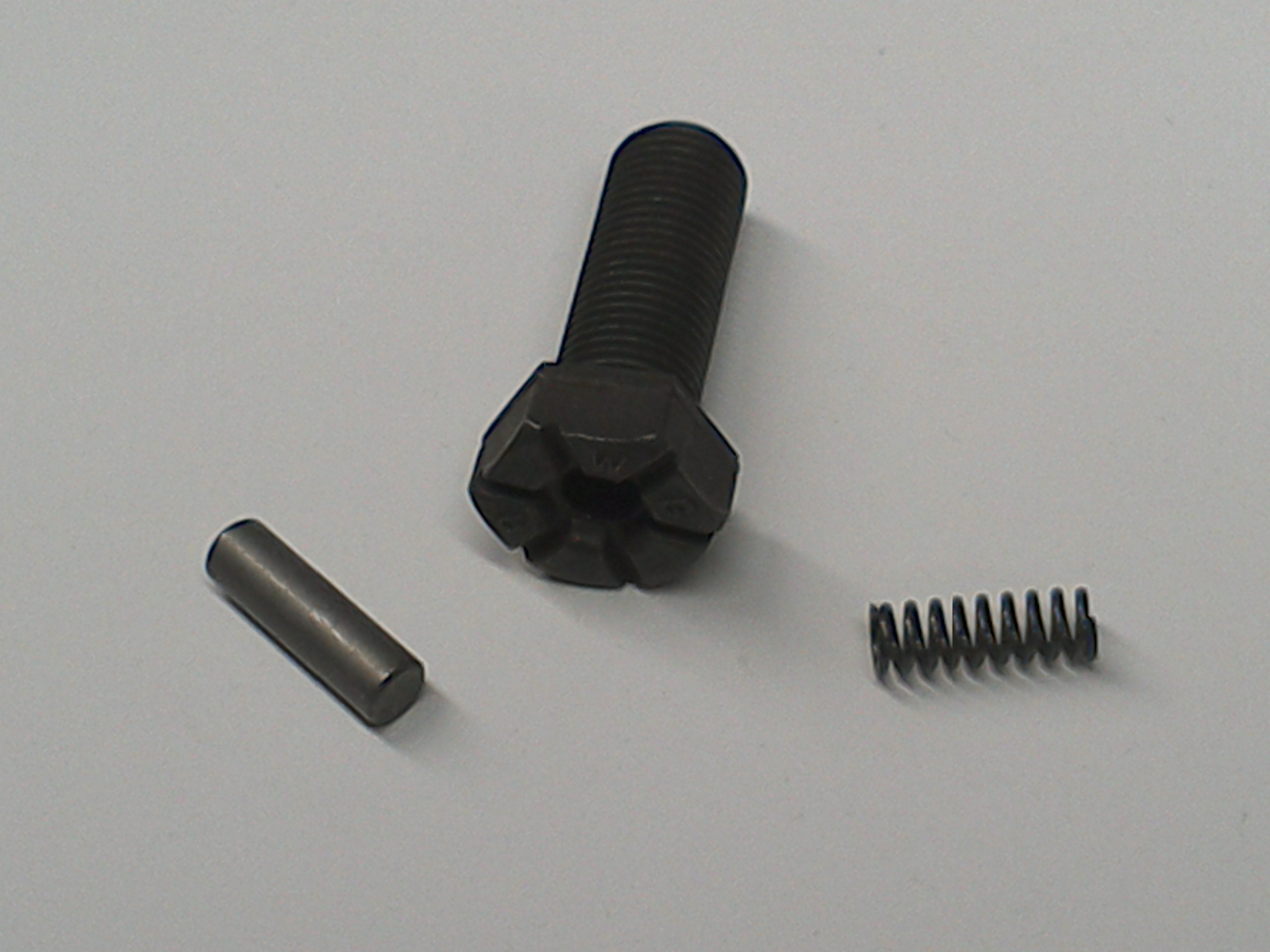
1) Have you pinpointed the valvetrain noise with a stethoscope, sounding tube or Steelman ChassisEar? Did you install the camshaft thrust bolt, spring and pin during the camshaft installation? This keeps the camshaft from walking forward, which can be an issue with these engines. No longer an OE part, the pieces were Mopar Camshaft Sprocket Bolt Kit #83502890. There is also the rubber timing cover chain slipper on engines through 1998. Did your timing cover and valvetrain have these pieces? This is the thrust bolt/spring/washer:
2) How many miles are on the refreshed engine now? Did you allow time for the PCM to "relearn" before the trouble symptoms returned?
3) Have you listened closely (with a hollow tube, stethoscope or ChassisEar) for the exhaust leak noise? Is the noise pinpointed to a specific area?
4) How old are the O2 sensor and injectors? Are your injectors the original Mopar units? Have you checked the fuel trim at an idle while the symptoms appear? Have you followed the fuel trim on this engine with a scan tool or live data stream at various engine speeds?
Point of interest: I bought an injector cleaning machine to test flow and performance of my '99 XJ's injectors at higher mileage. Installing new injector filters and ultrasonic cleaning the injectors made a significant difference. Clean, flow tested OEM injectors perform much better than inexpensive offshore replacement injectors that are often mismatched. For details on my tune-up and fuel injector service: https://4wdmechanix.com/jeep-4-0l-ignition-tune-up-and-injector-cleaning/.
5) TPS voltage, MAP and other sensors checked okay with a scan tool? What test method? The TPS has been replaced twice on our XJ in 191K miles. The upstream O2 sensor is a perishable as well, also replaced twice. The idle air control valve is another perishable that you need to remove and inspect. They get sooty and create idle and other issues. There are inexpensive offshore replacements at Amazon. Read the reviews.
6) Was the oil pan on the engine when you acquired it? Were you at any point able to measure the piston-to-cylinder wall clearance? I'm not suggesting that you dive that deeply unless necessary, but piston skirt clearance is an issue on Jeep 4.0L and 2.5L engines with coated skirts.
7) Pistons were new, but the wall clearance, piston skirt clearance and piston pin fit would be impossible to assess without dropping the pan and removing the head. Checking piston pin fit, rod truing and whether the bores are square to the crankshaft's centerline would require removal of the head, rods and pistons. If your engine was a higher caliber "reman", this should all have been done properly during the machining and fitting of parts. Did you get any history on the origins of the reman short engine? The 1991-95 blocks did not have the stiffer 'NVH' block webbing at the main areas nor did they have the NVH girdle between main caps. You lost that when your 1998 block was not reused. Some pre-'96 blocks allegedly had detrimental core shift (not toward the thrust side of the cylinders), which would make the engine noisier—especially with a rebore. When building a 4.0L block from the 1991-95 era, I would sonic test the block's cylinder walls before and after boring. But let's not leap to this kind of trouble yet. 0.030" is a reasonable bore size.
😎 Given the usual block decking, head surfacing (0.010" as you note), valve seat depths in the head, valve face machining and margins plus the valve stem lengths, you were very wise to consider valve spring fitted lengths! At this point, that's the only way to measure the valve keeper height above the valve spring seats. Whether the valve stem tips were machined or not, you compensated for valve stem height when you adjusted the lifter preloads with rocker arm shims—presumably for each of the 12 lifters, right? Customarily, valve lifter preload is set by correct pushrod lengths. Your shim approach could raise concerns about the rocker arm contact angles or binding at the valve stem tips—worth checking but not likely an issue. Make sure the rocker arm contact points align correctly with the valve stem tips. Also measure between the valve keepers and valve stem tips to see whether the stem tips were machined, which shortens that distance. Valve stem tip grinding is usually apparent.
That brings me to my most-recent effort to find the root cause of my annoyances. I speculated that my original valve springs were tired, so I replaced them with new OE-spec parts from Melling. That got rid of the low-RPM ping for good, and reduced valvetrain noise - but only for several days. The rough idle and exhaust noises persist. Based on that evidence, I further speculated that a combination of 300k miles and Bubba's Finest-Cheapest head work caused valve-seat recession, excessive spring installed-height, and thus too low valve seated-force. From what I read (correct me if wrong), the usual/cheap/easy tools provide only a relative measure of seated-force across the valves. Expensive setups are required to measure absolute seated force with accuracy and precision.
Your conclusions are each possible. Good that you're working with new Melling valve springs. Once you establish correct installed lengths, you should have confidence that the valves are seating properly. What does concern me, based on your scepticism about the valve job, is that valve guide clearance may be incorrect. (If guides were knurled, very old school, they will not hold up. If guides were not serviced at all, there could be excessive guide wear. When there is too much stem clearance, the valves will seat erratically. Loose guides can also be noisy and cause knocking that sounds like the rocker/valvetrain area or possibly a ping-like noise at the combustion chamber. This is not true "ping", knock or detonation, which would be the piston rocking and vibrating.
Traditionally, Jeep engines with cast-in guides required oversized valve stems and reaming the guides to correct for wear. For decades now, the aftermarket and common machine shop solution for guide wear is silicon-bronze guide liners that require machining the original cast-in guide and pressing the silicon-bronze guide liner sleeve into place. Finish ball driving is required for an exact fit. The ball driver sizes the guide liner bore while also securing the guide liner in place. Finished size is for a stock diameter valve stem.
I'm not sure whether you ran the engine long enough to create valve seat recession. If the original valves were reused, you'd have to see 1) how well the seats are centered on the valve faces, 2) whether three angles were cut to narrow the seat to proper width, and 3) the thickness of valve head outer margins if old valves were ground and reused. The seat valve contact widths and centering would be the main concerns here.
Your description of the spring installed heights points to a more accessible problem worth pursuing. As you note, the valves may not be seating with enough spring tension/pressure. A simple vacuum gauge test at the intake manifold can show guide wear and valve seating issues, including weak valve springs. I watch for a wavering gauge needle. This is a test to run before you perform any other work.
After a manifold vacuum test, here's what I would do without removing the cylinder head:
1) Remove the coil lead at the distributor cap. Do not crank the engine with the starter motor. Rotate the crankshaft by hand at the crankshaft damper bolt. Bring #1 piston to TDC on its compression stroke. (Work on only one cylinder at a time.) With the piston at or near TDC, a valve(s) cannot accidentally drop into the cylinder.
2) Use an air-hold at the spark plug hole with your compressor air line pressure keeping the valves in place. With the two valves closed, this should be easy to accomplish. Now you can loosen and remove the two rocker arms for the #1 cylinder. The valves will stay in position with the air pressure applied in the cylinder. (Sometimes the piston will drop in the cylinder if the piston was on either side of TDC. Air should still keep the valves in place.)
Note: You can buy an inexpensive air hold fitting at Amazon, Summit Racing, etc. Here is an example:
3) Use an over-the-top valve spring compressor to carefully remove the two valve springs. This is an OTC 4573, there are other compressors like this:

4) The valve stem seals will likely keep the valves in place. You can use clothes pins or soft-jawed small clamps on the valve stems as a backup. (You should not need to fuss with the stem seals unless they look damaged.) Temporarily disconnect or turn off the air supply to the air hold. This will release seating pressure on valves. Drop each valve down slightly to unseat it, and wiggle or measure for valve guide wear. (If you have a magnetic stand and dial indicator, you can take an accurate lateral stem movement reading.) If stem movement is excessive (well beyond the 0.003" FSM maximum; my limit would be 0.0025"), this could be your valvetrain noise. It could also cause rough valve seating and an erratic idle.
5) If valve guides are okay and not the source of trouble, re-apply the air hold pressure to hold the valves in position. Install the shims to establish the correct closed valve spring lengths/heights then install the valve springs, retainers and keepers. Be careful not to damage the stem seals...Now the spring tension is correct.
6) With #1 piston still at TDC and both valves seated (rockers not re-installed), run a cylinder leakdown test with the new spring heights. (If leakdown percentage looks high, there may be loosened carbon at the valve face. You may need to install the rocker arms and rotate the crankshaft to unseat the valves with the pressurized air applied. The air will clear debris.) I would like to see 12% leak on a fresh engine but would consider an engine still tune worthy up to 20-25% leakage. Uniform leak percentages are desirable here.
7) With #1 cylinder's rocker arms back in place securely, rotate the crankshaft until the next cylinder's piston is at TDC on its compression stroke. (You may need to view the ignition distributor rotor angle with the cap removed to find TDC on the compression stroke for each cylinder.) Repeat the sequenced steps performed at #1 cylinder. Once completed, you can move to the next cylinder(s) and perform the same steps. It may be easier to do this work in the firing order for the cylinders. If so, the cylinder sequence will be 1-5-3-6-2-4.
Instead of seated-force, I decided to measure spring installed-height, using a tool that fits in place of the spring. I transferred each measurement to a mic as I did not trust the cheap tool's scale. I found the installed-heights to be generally about 0.020 over stock 1.640 spec, with several at 0.030 and #1 exhaust at 0.053 over! My math shows 0.053 over translates to approx 15% too low of seated-force, far outside spec. Incidentally, the sources I found show stock seated-force for a '98 at 70-79lbs, vs the 61-69lbs figure you quoted. And yes, I had the springs out but neglected to measure spring pocket dimensions (it's my 2nd rodeo).
The current installed spring lengths/heights raise some concern. Usually the symptom would be valve float at higher rpm, but idle seat pressure could have an effect, too. (Again, demystify this with a simple vacuum gauge test at the intake manifold with the engine idling. Listen for roughness that coincides with needle waver.) From there, rule out whether the valve guides are loose. If the valve work was with old valves and slight stem wear, with either no guide work or the knurling of cast-in guides, the valve guides could be a problem. It comes down to valve seal and seating at the speeds you hear noise or experience engine roughness.
Note: If you have the machine shop invoice, look down the parts list for valve guide liners. Also see whether the shop installed new valves or refinished the original valves. Sometimes a shop will install new exhaust valves and refinish the intakes. Sometimes they do all new valves. Other times, they use no new valves. Major reman shops use all new valves. Volume cost for 4.0L valves makes it cheaper to replace the full set rather than waste labor time refacing old valves.
At this time, my theory is that low valve seated-force (especially on #1 exhaust) can be overcome, under some circumstances, by lifter pump-up - resulting in a valve that does not close fully, or not at the intended point. However, I don't know how sensitive my 4.0L's valvetrain is to valve seated-force, and if the symptoms I'm observing are reasonable indicators of a problem in that area. With the holidays approaching, I'll have time to pull a valve spring and measure the pocket dimensions. I'll post my measurements here to benefit the next cowboy. And thank you for your recommendation on shims.
Again, I'm not fixed on the spring pressures though they need to be corrected while you're inspecting for guide wear...From your comment on pocket dimensions, are you already using an air hold and topside valve spring compressor?
Check the valve guides for wear and also note whether the machinist installed silicon bronze guide inserts. If not, the cast guides were either not serviced or may have been "old school" knurled. Knurling rolls a spiral down the original cast guide that raises the material and essentially shrinks the bore diameter. Once sized, the rolled spiral has only half the valve stem contact surface. Knurled guides, for this reason, wear or deteriorate much faster than the original guide surface or a silicon bronze guide liner. To your point, the practice is still used on slow rpm engines like older tractors. Review the invoice.
Some footnotes and takeaways: If you installed the thrust pin and spring at the timing sprocket bolt, I would rule out camshaft fore/aft walk (another knock cause) or lobe-to-lifter wear issues, especially with a new cam, lifters and timing set if properly lubricated during installation. The concern around piston skirt clearance cannot be verified without dropping the pan. If you're confident about the short-block's history, originality and build quality, the piston fit and bore machining should not be an issue. 0.030" oversize is standard for the reman industry, it's the common, least expensive replacement piston size. Even with a core-shifted or poorly webbed block and no girdle, noise should not be at the "warranty claim" level. The bore size would be unlikely to exaggerate the OEM noise level. This short engine, by nature, is noisier but not to the excess you have experienced...Systematically separate the mechanical issues from electronic fuel-and-spark management related possibilities.
Thanks for listening!
Happy to listen...Your methodical troubleshooting deserves attention.
Keep us posted!
Moses
On 12/6/2022 at 8:08 AM, SomeBuckaroo said:
-
Julio...Were you able to identify the thread size of the pressure test port plug? Take the plug and your pressure gauge to a NAPA store with a good assortment of fittings. You should be able to put together the needed fittings. If you are successful, please let us know the thread size and type of threads at the port (female) end.
Chrysler offered a TBI "Diagnostic Connector" for testing the TBI fuel pressure. This connector (shown below) uses a Schrader valve and common EFI Schrader valve connection fitting. (EFI fuel rail pressure testing kits usually attach to a Schrader test valve at the fuel rail. For those on a budget, Harbor Freight has affordable EFI pressure testing kits like this one that will fit most applications: https://www.harborfreight.com/basic-fuel-injection-service-kit-64939.html.) The Chrysler/Jeep adapter to a Schrader valve is Mopar part number 83501572.
I'm certain this adapter is only available used (maybe eBay) or as an NOS part (again, try eBay). There is likely an aftermarket equivalent if you can determine the TBI port thread size. A Schrader type fitting would enable quick testing at any time. AMC and Chrysler should have made this adapter a permanent part of the TBI assembly. This is a common test method for EFI/MPI fuel rails. You can see how the connector replaces the TBI test plug in this illustration:

This is an illustration of the Mopar 83501572 adapter (or aftermarket equivalent) that works with an EFI Schrader valve test kit. This illustration is listed in the Mopar parts catalog for 1988 Jeep 2.5L YJ and XJ engines and used on other applications of the AMC/Chrysler/Jeep 2.5L TBI engines.
Aftermarket Schrader valve adapters and EFI service kits show up at Amazon and elsewhere. Make sure the Schrader is rated for fuel use. If you can find an adapter/fitting that will fit the TBI test port thread, you will need a coupler to connect the adapter to your gauge.
Otherwise, the pressure tester that you purchased can be used by installing a temporary brass or steel "T" fitting between the fuel supply line and the TBI unit's fuel inlet fitting. The fuel would flow from the fuel supply line to the TBI unit through the brass or steel "T"; the third port of the "T" goes to your gauge. You may need the "T" plus a few extra fittings to create this "adapter". You can even set up this temporary "T" at the engine side of the fuel filter if that's easier or preferred. The results should be close enough.
If the return line to the fuel tank is not obstructed, you should get the same pressure reading at this "T" as you would get at the test port. Why? Because the TBI regulator lowers the available fuel pump pressure by continuously flowing excess fuel to the fuel tank via the return line. The pressure reading at the "T" should be in the 14-15 psi range when the fuel pump and engine are running.
You mention not having an adjustment screw on the regulator's base. Illustrations in the 1989 FSM show a recessed screw that may not be readily visible. If you have a small mirror, see whether you have a screw that is flush or inset at the base of the bowl. If not, as you suggest, the Mopar parts catalog shows a replacement regulator that has a preset spring tension and a ball holding the spring in place. It looks like the illustration below and does not have the threaded adjuster screw shown in the FSMs. The spring and ball set a fixed adjustment on the fuel pressure regulator. There may be aftermarket versions that do not use the ball and have the smooth bowl you describe...That spring is inside the bowl or there is no lower (smaller) spring at all? In the design below, the small spring either sets a fixed pressure or acts as a damper—or both:

As long as you're getting the 14-15 psi at the adapter "T" between the fuel supply line and TBI unit (or at the engine side of the fuel filter), you should be good. If pressure is as high as the fuel pump pressure, or well above the 14-15 psi, check the return line flow into the fuel tank for an obstruction. Once normal TBI fuel pressure is confirmed or reset, I would check the TPS (throttle position sensor) setting.
The TPS is adjustable and should be adjusted to the voltage settings found in the FSM. Many owners and technicians mess around with the TPS to get a stable or desired idle. The TPS is like a rheostat switch and must have the right voltage settings and readings for each angle of the throttle valve. Often, adjusting the TPS to the right voltage outputs at the specified throttle valve angles will reduce or eliminate an over-rich or a lean fuel mixture.
I would also check vacuum line routing to the EGR valve and test the EGR valve function directly, using a hand vacuum pump attached directly to the EGR valve with the engine idling. The EGR diaphragm can be tested for a leak with the hand pump and gauge. There should be a distinct effect on the idle when the EGR valve opens and closes.
If the EGR diaphragm will not hold vacuum, replace the valve. If the EGR is original and not responding, but it does hold vacuum, I would remove the valve and either clean its exhaust ports or replace the unit. I clean an EGR by soaking the metal base and valve plunger in carburetor cleaner then removing carbon. (A soda blaster might do a reasonable job on light carbon or scale.) Do not allow carburetor cleaner to get into or near the diaphragm. Carburetor cleaner will warp or destroy a diaphragm.
Let us know your findings...
Moses


.jpg.4df1d246cfae668033b95f5330d84a33.jpg)
.jpg.06f63b9dbba2f1debfc6c981f14de67e.jpg)
.jpg.0bca2c6172b4dc5e43474a7606ad293b.jpg)


-1.jpg.b7f7095bb546f660977ee20c328b2159.jpg)
-1.jpg.6a708282b09b70f6f5ae78e4cdbcf92a.jpg)


Question regarding installation of aftermarket oil pressure and voltage gauges
in Toyota 4WD Pickup, Hi-Lux, Tacoma, Tundra and 4Runner
Posted
A very neat, clean and pristine installation! Years ago, I had a 1955 Ford F100 pickup that was a testbed for engine and transmission swaps. I made mounts that fit to the factory engine and transmission mounting positions. This required virtually no modifications other than a few drilled holes. I eventually did restore that truck to a near stock condition.
At the time, these now classic '53-'56 Ford F100 pickups were plentiful and popular for "hot rodding"—often brutishly modified. I can appreciate your concern for authenticity and option to restore your valued 1982 Toyota Hilux 4x4 to its original form.
You have a classic truck. The early 4x4 Toyota compact pickups with a beam front axle featured the indestructible "300,000 Mile Club" 22R engine. I had three FJ40 Land Cruisers: 1971, 1976 and 1978. The latter two were extensively modified OFF-ROAD Magazine project vehicles, the '76 in the late eighties then the '78 in the mid-nineties. The '78 was a floor feature at the SEMA Show, Las Vegas...Toyota had it going on! Enjoy your truck.
Moses